1500 W clamping at the 40 V rail
The 1.5KE47CA A0G: Its 40.2 V reverse standoff voltage places it on a 36-40 V DC bus — a 48 V telecom supply or a 36 V battery line — where the 64.8 V clamp catches transients before they reach downstream converters. The 24 A peak pulse current rating (Ipp at 10/1000 µs) tells you the diode can absorb a 24 A surge without exceeding the 64.8 V clamp — a direct input for fuse coordination and MOV sizing in the same rail.
Breakdown window and bidirectional clamp
Breakdown voltage starts at 44.7 V minimum — this is the knee where the Zener begins conducting. Below that, the 40.2 V standoff rating guarantees the diode stays off the line at nominal bus voltage, drawing only leakage. The 64.8 V clamp is the voltage the load sees during the surge; a downstream 75 V-rated MOSFET has 10 V of headroom. Bidirectional channels: 1. One device clamps both polarities — no need to series two unidirectional parts. This matters for AC-coupled signal lines or DC rails where reverse-voltage events are possible.
DO-201 axial lead — board-fit reality
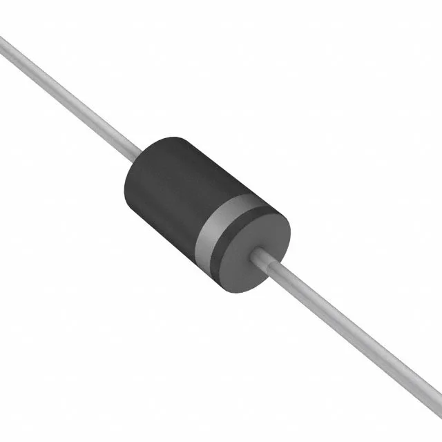
Through-hole DO-201AA (DO-27, Axial) package. The DO-201 body is 5.3 mm diameter, 7.6 mm long — the leads are 1.0 mm diameter tinned copper. The 1500 W rating assumes the leads are soldered into a PCB with adequate copper area for heat sinking; the junction-to-lead thermal path carries the pulse energy. The 175°C max junction allows the device to absorb repetitive pulses in a hot enclosure — a 105°C ambient still leaves 70°C of junction margin for the pulse.