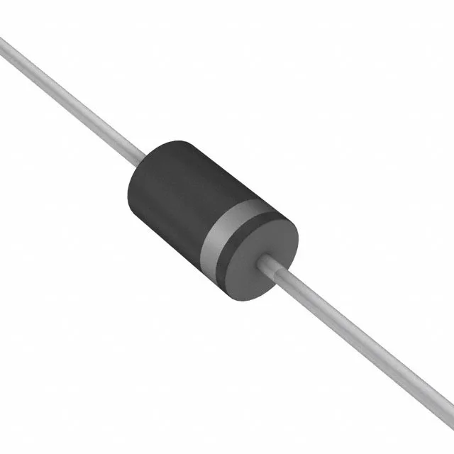
1500 W peak pulse, 300 V standoff — the clamp voltage and the transient it stops
The 1.5KE350A A0G: The 482 V clamp ceiling is the number that matters for downstream component stress: any device rated below that voltage on the same rail sees the full clamp voltage across its terminals during the event. A 400 V-rated MOSFET, for example, would be outside its safe operating area if the TVS fires.
DO-201 axial package — through-hole mounting and thermal path
Housed in a DO-201AA (DO-27) axial-lead package, the 1.5KE350A A0G mounts through-hole. The body is cylindrical with wire leads — the lead-to-body thermal path is the primary heat removal route during a pulse; the board copper landing pads on both sides of the axial body sink the heat after the event. The 175°C TJ max means the device can absorb repeated pulses at elevated ambient without derating the peak power — provided the average power stays within the thermal limit of the lead-to-board interface.