Clamp voltage and the protection window
The 1.5KE100A A0G: Its reverse standoff voltage of 85.5V means the protected line sees no leakage at normal operating voltage up to that level; breakdown starts at 95V minimum, and the clamp voltage at peak pulse current is 137V maximum. That 137V clamp is the voltage the downstream component must survive — the TVS absorbs the surge energy and holds the line below that ceiling.
Peak pulse current and waveform reality
A shorter, faster transient (8/20µs) will drive a higher peak current into the same clamp voltage; the 1500W rating is the energy envelope, not a hard current limit. For a 24V bus or a 48V telecom rail, the 85.5V standoff provides margin above the nominal rail plus ripple. At the high end, leakage current at standoff voltage rises, but the clamping behaviour remains stable within the Zener breakdown region.
Package and board integration
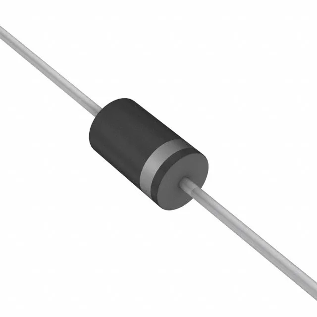
Supplied in a DO-201AA (DO-27) axial-lead through-hole package, the 1.5KE100A A0G comes in Tape & Box (TB) for hand-insertion or machine-insertion with formed leads. The axial body is 9.1 mm long typical, with 1.3 mm diameter leads — the hole diameter on the PCB should be 1.0 mm to 1.2 mm for a reliable solder fillet. No power line protection means this part is intended for signal and DC rail protection, not AC mains primary-side clamping.