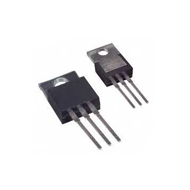
What the TIP115 does in a power-switching circuit
The TIP115 is a PNP Darlington transistor rated for 60 V collector-emitter breakdown and 2 A continuous collector current — a combination that covers relay, solenoid, and small-motor switching on a 24 V or 48 V industrial rail. Its Darlington configuration delivers a minimum DC current gain of 1000 at 1 A collector current and 4 V Vce, so a 2 A load needs less than 2 mA from the base drive — a standard logic gate or microcontroller pin can switch it directly without a pre-driver stage. The TO-220-3 through-hole package has a metal tab for heatsinking; the junction temperature range of -65°C to 150°C exceeds the typical industrial -40°C to 125°C envelope, giving margin in outdoor or engine-bay environments.
What the 2 A collector rating means for your load
The 2 A Ic maximum is a continuous rating at 25°C case temperature; above that, derate per the datasheet's power-dissipation curve. A 50 W absolute maximum power limit means the product of Vce(sat) and Ic must stay within that ceiling — at 2 A the Vce(sat) of 2.5 V typ at 8 mA base drive already dissipates 5 W, requiring a heatsink. The 2 mA collector cutoff current at maximum rated voltage is the leakage floor — negligible in most switching applications, but worth noting if the load is a high-impedance input that could be falsely triggered by leakage.
Package and mounting note
TO-220-3 is a standard through-hole power package with a 0.100-inch pin pitch. The centre pin is the collector, the left pin (with the tab) is the base, and the right pin is the emitter — verify the pinout against the datasheet before populating the board.