What the 5 mA gate trigger means for your drive circuit
The T405-600B is a logic-level (sensitive-gate) triac with a maximum gate trigger current of 5 mA and a maximum gate trigger voltage of 1.3 V. The 4 A RMS on-state current rating sets the continuous load ceiling. In a 240 VAC line, that is roughly 960 VA of resistive load; for inductive loads like a small fan or solenoid valve, derate to about 60-70% of the RMS figure to stay inside the junction temperature limit.
Package and rework — DPAK on the bench
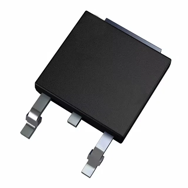
Housed in a DPAK (TO-252) surface-mount package with a single exposed tab on the back side. The tab is the MT2 terminal and carries the thermal path to the board copper. The three-lead footprint is standard and reworkable with hot air — the tab solders to a pad on the PCB, so the board layout should include a thermal relief pattern that lets the joint reflow without wicking all the heat into the ground plane. Supplied in tube, not tape-and-reel. For a pick-and-place line, plan to transfer parts into a tape carrier or hand-place them for prototype runs. The tube packaging is fine for bench builds and small batches.
Surge and holding current — the real-world limits
Non-repetitive surge current is 30 A at 50 Hz and 31 A at 60 Hz. That covers the inrush from a 100 W incandescent lamp or a small motor start, but not a capacitor-input power supply — the surge rating is a half-cycle peak, not a repetitive event. Maximum holding current is 10 mA. Below that load current, the triac drops out of conduction at the next zero-crossing. For a very light load like a 5 W LED driver, the holding current may not be met and the triac will not latch — size the minimum load to stay above 10 mA.
Active production and compliance
It is a current-production part from STMicroelectronics, fully ROHS3 compliant.