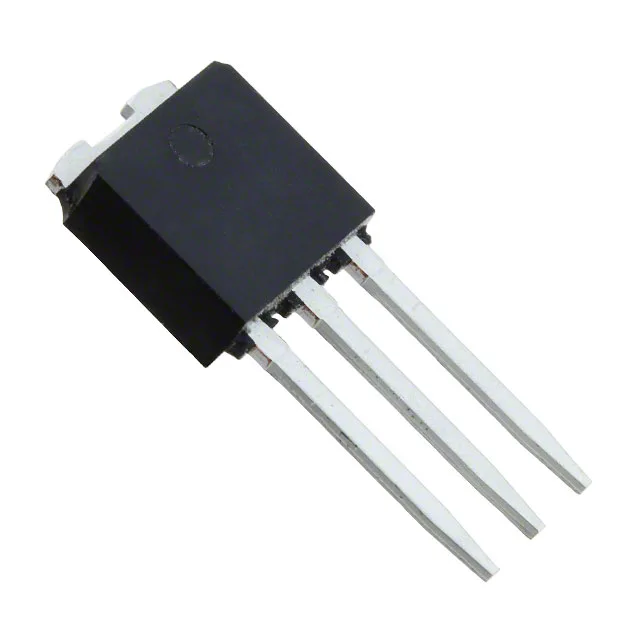
950 V N-channel in a TO-251 — what it is for
1.25 Ohm on-resistance — conduction loss at the operating point
At the full 9 A rating the actual on-resistance will be higher due to self-heating — the datasheet's normalised curve shows Rds(on) roughly doubling at 150 °C junction. For a 100 W flyback running at 0.5 A average drain current, that 1.25 Ohm contributes under 0.3 W conduction loss; the same part in a 3 A continuous load would dissipate over 11 W, pushing the 90 W package limit.
13 nC gate charge — drive it with a small driver
Input capacitance is 450 pF at 100 V drain bias — the Miller plateau is short, so the part can switch several hundred volts in under 50 ns with a proper layout. That matters for reducing turn-on crossover loss in hard-switched topologies.
-55 to 150 °C — field-replaceable in harsh spots
The TO-251 package has a tab that can be bolted to a chassis or heatsink — on a site repair, swapping this part is a soldering-iron job, no hot-air station needed. The gate threshold is 5 V max at 100 µA, which means a standard 12 V gate drive from a PWM controller will saturate it fully.