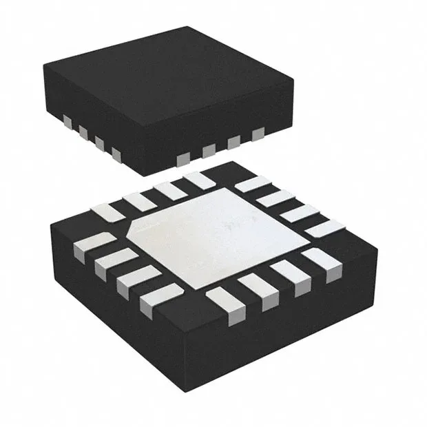
STMicroelectronics STSPIN250 — DC-DC Power Modules

STSPIN250 Brushed DC Motor Driver, 2.6 A, 1.8-10 V Load

MPNSTSPIN250
End of Life

STMicroelectronics STSPIN250, Series STSPIN2, Driver - Fully Integrated, Control and Power Stage, Power MOSFET, PWM Interface, 2.6A Output, 1.8V~10V Load, 0V~5V Supply, -40°C~150°C, 16-VFQFN Exposed Pad.

$2.68Ref. price · indicative, final on quote
Packaging16-VFQFN Exposed Pad
RoHSROHS3 Compliant
SeriesSTSPIN2
Independent supplier — new & surplus stockAuthenticity-screened · ESD-safe packingListing updated Aug 2026

Specifications

STSPIN250 specifications
ParameterValue
SeriesSTSPIN2
MountingSurface Mount
Motor type - AC, DCBrushed DC
Voltage - load1.8V ~ 10V
Voltage0V ~ 5V
Output current2.6A
InterfacePWM
Operating temperature-40°C ~ 150°C (TJ)
PackageTape & Reel (TR); Cut Tape (CT)
FunctionDriver - Fully Integrated, Control and Power Stage
TechnologyPower MOSFET
ApplicationsGeneral Purpose
Case16-VFQFN Exposed Pad
Output configurationHalf Bridge (4)

Product details

The STMicroelectronics STSPIN250 is a fully integrated brushed DC motor driver that combines control logic and a power stage in a single 16-VFQFPN package. It integrates four N-channel Power MOSFETs configured as half bridges, giving you a complete H-bridge for bidirectional motor control with current recirculation. The PWM interface accepts logic-level signals directly from a microcontroller or timer, so no external gate driver or level shifter is needed for the control side. The load supply range spans 1.8 V to 10 V. The logic supply runs from 0 V to 5 V. Continuous output current is rated at 2.6 A. It is rated for general-purpose applications, not automotive-qualified (no AEC-Q100 listed), but the temperature grade itself is wide enough for many harsh industrial or automotive-adjacent builds.

The 2.6 A continuous output is the part's headline rating. For a brushed DC motor, that figure determines the stall current the driver must survive without thermal shutdown. The 16-VFQFPN package with exposed pad helps pull heat into the PCB copper plane. The four half bridges give you independent control of each MOSFET pair, so you can implement forward, reverse, coast, and brake modes with standard PWM signals. No external commutation logic is required — the PWM interface handles it directly.

No surplus-broker dependency required. The series is STSPIN2, which includes other brushed DC drivers with similar pinouts and voltage ranges. If you are dual-sourcing for supply resilience, verify the pinout and thermal pad compatibility before substituting.

Frequently asked questions

What is the output current of STSPIN250?

The STSPIN250 is rated for 2.6 A continuous output current. That is the nominal current the driver can deliver to the motor under normal operating conditions; stall current or start-up transients may exceed this and require duty-cycle or thermal management.

What supply voltage does STSPIN250 require?

The load (motor) supply voltage range is 1.8 V to 10 V. The logic supply for the PWM interface runs from 0 V to 5 V. A 12 V brushed DC motor is outside the load voltage range and will damage the part.

Can STSPIN250 drive a 12V brushed DC motor?

No. The load voltage range is 1.8 V to 10 V. A 12 V motor supply exceeds the rated maximum and will overstress the driver. Use a higher-voltage part such as the STSPIN240 for 12 V applications.