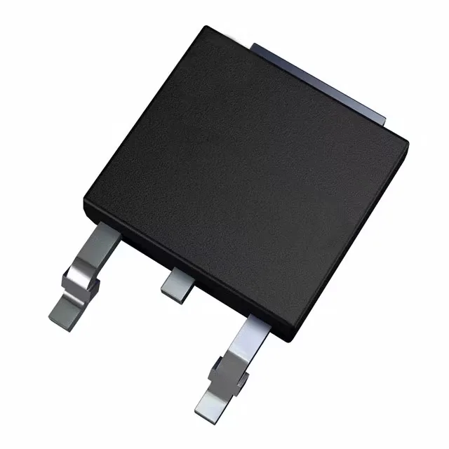
Zero-recovery SiC diode for automotive power stages
What the 0 ns trr means for the switching loop
The reverse recovery time is listed as 0 ns — this is not a rounded-down small number; it is the property of a majority-carrier Schottky structure. In a hard-switched boost converter or totem-pole PFC stage, the diode's turn-off contributes no reverse-recovery charge, so the MOSFET or IGBT does not have to absorb that energy. The 414 pF capacitance at 0 V, 1 MHz is the only charge that needs to be moved per switching cycle. The 80 µA reverse leakage at 650 V is specified at 25°C — expect it to rise with junction temperature, but the SiC wide-bandgap material keeps the increase manageable compared to a silicon fast-recovery diode at the same voltage class.
DPAK footprint and thermal path
The TO-252-3 DPAK package has the tab as the cathode terminal — the large copper pad on the PCB is the primary heat path. The 8 A average rectified current rating assumes that pad is sized per the manufacturer's recommended land pattern; a 1-inch² 2-oz copper pad is the typical starting point for a 175°C junction target in still air.
No official successor or second-source alternate is listed on the STMicroelectronics cross-reference for this base product number.