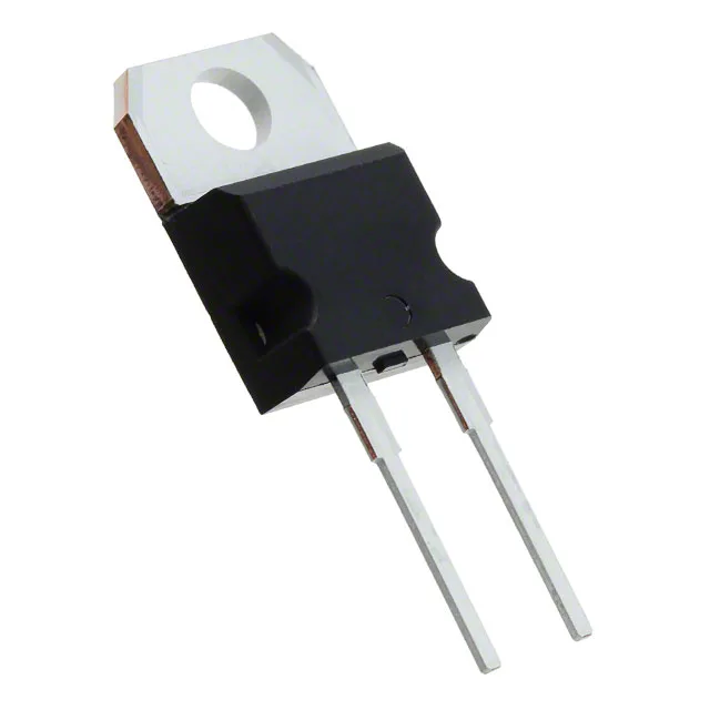
SiC Schottky with zero recovery charge — why the switching node stays cool
The STPSC20065DY is a 650 V, 20 A silicon carbide Schottky diode in a TO-220AC through-hole package. Its zero reverse recovery time (trr = 0 ns) means the diode never stores minority carriers — every turn-off event is instant, so the hard-switched MOSFET or IGBT in the same leg sees no reverse-recovery current spike and no associated power loss. For a 20 A boost stage in an automotive on-board charger or a DC-DC converter, that translates directly into lower junction temperature in both the diode and the switch, or a smaller heatsink for the same thermal budget.
Automotive qualification and the 175°C junction ceiling
AEC-Q101 qualification and the Automotive grade listing mean this diode has passed the stress tests — HTRB, H3TRB, TC, and the rest — that the automotive tier demands for under-hood and transmission-mounted power stages. The -40°C to 175°C junction temperature range covers the full mission profile of a traction inverter or an engine-bay DC-DC: cold crank at -40°C, continuous operation at 125°C ambient, and the 175°C peak during a stalled-coolant event. The 1.45 V forward drop at 20 A is the SiC Schottky trade-off — higher than a silicon ultrafast at low current, but the zero recovery charge means the total loss at switching frequency is lower.
For a production BOM that has already qualified this diode, the sourcing desk can plan multi-year builds without an obsolescence-driven redesign cycle. The ECOPACK®2 series designation confirms the package is halogen-free and meets the current environmental compliance thresholds.
Reverse leakage and capacitance — the cold-side limits
At the rated 600 V reverse bias, the maximum leakage current is 150 µA. This is the SiC wide-bandgap advantage — a silicon ultrafast of the same voltage class would leak several times more at 125°C junction. The 1250 pF capacitance at 0 V, 1 MHz sets the switching loss from the diode's own junction charging: in a 100 kHz boost stage, that capacitance adds roughly 0.5 W of loss, which is accounted for in the thermal design of the heatsink.