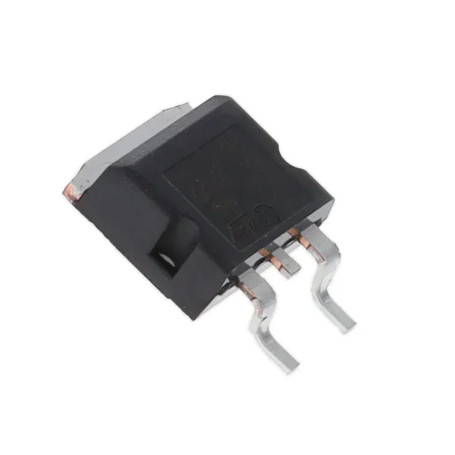
SiC Schottky — zero-recovery switching for automotive power stages
The STPSC10H065GY-TR is a silicon carbide Schottky diode from STMicroelectronics, rated for 650 V reverse voltage and 10 A average forward current. This eliminates the reverse recovery loss component entirely, which is the dominant switching loss mechanism in standard ultrafast silicon diodes. For a PFC boost stage or LLC secondary rectifier running at 100 kHz or higher, removing that loss can cut total diode dissipation by half compared to a silicon FRED of the same voltage class.
Forward drop and leakage — the thermal budget drivers
Maximum forward voltage is 1.75 V at 10 A and 25 °C junction. That 17.5 W peak conduction loss at rated current is the primary heat source — the 0 ns switching loss adds negligible thermal burden, so the heatsink sizing is essentially Vf × Iavg. Reverse leakage is 100 µA at 650 V, junction temperature unspecified in the max rating. SiC leakage rises more slowly with temperature than silicon, but at 175 °C junction the leakage current can multiply several times — still typically below 1 mA, which is manageable for the bias network in a PFC controller. Capacitance at zero bias is 480 pF at 1 MHz. This is the output capacitance the MOSFET or IGBT sees as the diode commutates — a 480 pF Coss adds about 24 nC of charge per switching cycle at 400 V bus, which the driver must supply. That figure is in line with other SiC 10 A / 650 V parts.
D²PAK footprint — thermal and mechanical fit
The diode is housed in a D²PAK (TO-263AB) surface-mount package with the anode on the two leads and the cathode on the exposed tab. A 2 oz copper pour of at least 600 mm² on the top layer is typical for 10 A continuous operation in still air. Standard MSL for this package family is MSL-3, so a 24-hour bake at 125 °C is required before reflow if the moisture barrier bag has been opened for more than the floor-life period.