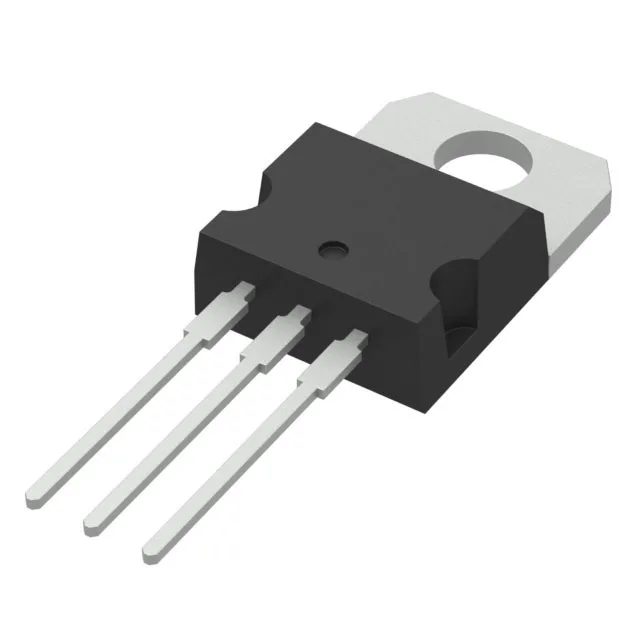
600 V N-channel MOSFET for high-efficiency switched-mode power supplies
The MDmesh M6 process delivers a low typical on-resistance figure of merit — the 280 mOhm max at 10 V gate drive combined with a gate charge of 16.8 nC at 10 V reduces both conduction and switching losses, which is where the efficiency gain shows up in a 100–300 W power stage.
280 mOhm on-resistance — what it means for conduction loss
The max Rds(on) of 280 mOhm at 6.5 A, 10 V is the number to use for worst-case conduction loss calculations. At 6.5 A drain current, that resistance dissipates about 12 W — well within the 110 W power dissipation limit at 25°C case, but the junction temperature derating needs to be factored in for your actual operating current and ambient. The MDmesh M6 process gives a positive temperature coefficient on Rds(on), so paralleling devices shares current naturally, but the thermal design still needs to keep Tj below 150°C.
That keeps the gate drive power low — at 100 kHz switching, the gate drive loss is roughly 17 mW. The low input capacitance of 650 pF at 100 V drain-source also helps the driver slew the gate voltage quickly, minimizing cross-conduction during hard-switched transitions.
The TO-220-3 through-hole package with the tab as the drain connection is the workhorse for medium-power through-hole designs. The 110 W maximum power dissipation assumes the tab is soldered to a heatsink with adequate thermal interface. For a 13 A continuous drain current, the junction-to-case thermal resistance will be the limiting factor — the package itself handles the current, but the heatsink area and airflow determine whether the junction stays below 150°C at full load.
Sourcing and supply position
For BOM stability in a new design, this is a low supply-risk choice — no imminent obsolescence to watch.