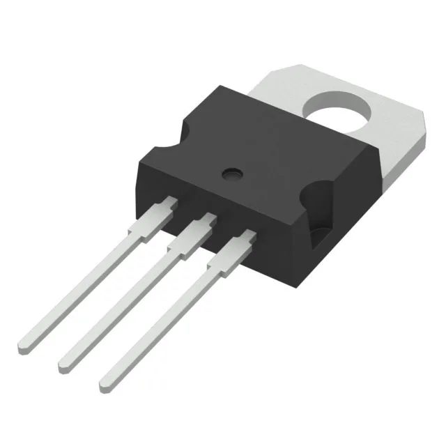
40 V, 120 A — the low-voltage switching workhorse
The STP180N4F6: The 40 V Vdss puts it squarely in the 12 V and 24 V automotive, battery-management, and low-voltage power-conversion sweet spot — the margin above a 12 V rail is generous, but it is not a 60 V or 80 V part for 48 V bus applications. The 120 A Id rating in a TO-220-3 package tells you the die is large and the thermal path through the tab is the limiter; the buyer should plan on a heatsink sized for the load current and ambient.
Gate drive at 4.5 V — logic-level compatibility
Rds(on) is specified at both 4.5 V and 10 V gate drive, meaning the MOSFET can be turned on hard from a 5 V microcontroller output or a standard gate-driver IC without a separate 10 V rail. The 4.5 V drive level is the lower threshold for designs that want to simplify the gate-drive supply — but the on-resistance at 4.5 V will be higher than at 10 V, so the conduction loss trade-off needs to be checked against the load current.
190 W dissipation — heatsink sizing is non-negotiable
In practice, the junction-to-case thermal resistance (not listed here but implied by the Pd rating) means the buyer must size the heatsink and airflow to keep the case temperature within the derating curve. The TO-220-3 package with a standard hole pattern mates with clip-on or screw-mount heatsinks; the tab is the drain, so the heatsink may need electrical isolation or the system must tolerate the tab at drain potential.
No last-time-buy planning is needed for the BOM line.