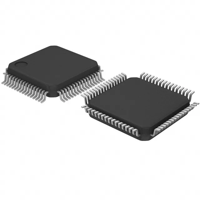
80 MHz Cortex-M4 with 1 MB Flash — what the memory and speed mean for the firmware budget
The STM32L496RGT3: The 1 MB Flash is organized as 1M x 8, and the 320 KB RAM as 320K x 8 — enough for dual audio buffers or a moderate-size GUI on a QVGA display. The 80 MHz core clock is the practical ceiling for this part.
The 125°C ceiling means the junction temperature stays inside the safe operating area.
Supply range and power rail design — 1.71V to 3.6V
The VDD range from 1.71V to 3.6V covers the full discharge curve of a single Li-ion cell (4.2V down to 2.7V with a regulator) and also runs directly off a 1.8V logic rail without a separate LDO. The brown-out detect reset (BOR) is programmable in four thresholds across this range, so you can set the reset trip at 1.8V for a 1.8V-only design or at 2.7V for a battery-powered system that needs to shut down gracefully before the cell drops below the safe discharge floor.
Peripheral set and connectivity — what is on the bus
The STM32L496RGT3 brings out CANbus, USB OTG (FS), QSPI for external Flash/PSRAM, SAI for I2S audio, and multiple UART/USART, I2C, and SPI ports. The 52 I/O pins in the 64-LQFP package leave enough for a parallel LCD data bus (8-bit or 16-bit), an external memory chip, and a few sensors or actuators. The LCD controller peripheral drives a segment LCD directly — useful for industrial panel meters or medical device displays without a separate driver IC.
Package and footprint — 64-LQFP 10x10 mm
The 0.5 mm pitch means the PCB fab needs a 0.25 mm trace/space capability, which is standard for any low-cost prototype house.
ROHS3 compliant per. No last-time-buy exposure.