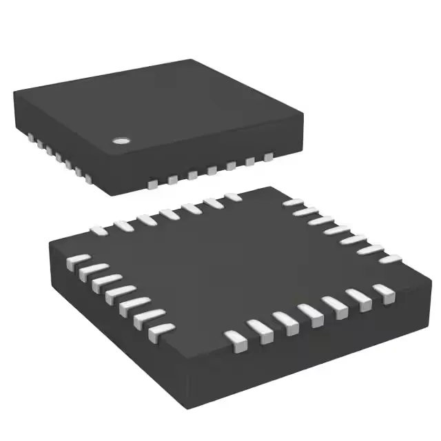
STMicroelectronics STM32L021G4U6 — Microcontrollers & Processors (MCU / MPU / DSP)

ST STM32L021G4U6 ARM Cortex-M0+ MCU, 32MHz, 16KB Flash

MPNSTM32L021G4U6
Active

STMicroelectronics STM32L0 series, ARM® Cortex®-M0+ 32-bit MCU, 32MHz, 16KB Flash, 2K x 8 SRAM, 512 x 8 EEPROM, 1.65V-3.6V, -40°C to 85°C, 28-UFQFPN (4x4), 24 I/O.

$1.6058Ref. price · indicative, final on quote
StockContact for availability
MOQ1 pcs
  • 100% new & originalTraceable channels only — no refurbs, no pulls, no remarked parts.
  • Date & lot codes on quoteStated per line before you commit; label photos on request.
  • MSL-compliant ESD packingMoisture-sealed bags with indicator cards; reels photo-verified.
  • PayPal buyer protectionPay by T/T, PayPal or Payoneer — card payments covered end to end.

Specifications

STM32L021G4U6 Technical Specifications
ParameterValue
SeriesSTM32L0
Mounting typeSurface Mount
Oscillator typeInternal
Program memory typeFLASH
Voltage - supply (Vcc (Vdd))1.65V ~ 3.6V
Operating temperature-40°C~85°C(TA)
Speed32MHz
PackageTray
RAM size2K x 8
Core size32-Bit Single-Core
EEPROM size512 x 8
PeripheralsBrown-out Detect/Reset, DMA, POR, PWM, WDT
ConnectivityI²C, IrDA, SPI, UART/USART
Number of i (O)24
Core processorARM® Cortex®-M0+
Case28-UFQFN
Data convertersA/D 10x12b
Program memory size16KB (16K x 8)

Product details

ARM Cortex-M0+ at 32 MHz — the low-power sweet spot

The STM32L021G4U6: 16 KB Flash, 2 KB SRAM, and 512 bytes EEPROM on-chip.

Peripheral set and I/O — 24 pins, 10-channel 12-bit ADC

24 I/O lines in a 28-UFQFPN (4x4 mm) package. 10-channel 12-bit ADC on board.

STMicroelectronics lists the STM32L021G4U6 as Active.

Frequently asked questions

Can STM32L021G4U6 be programmed using standard ARM toolchains?

Yes. The ARM Cortex-M0+ core is supported by all major ARM toolchains — Keil MDK, IAR EWARM, GCC (ARM Embedded), and STM32CubeIDE. Programming and debug use the standard SWD interface.

What is the maximum operating frequency of STM32L021G4U6?

The listed maximum speed is 32 MHz. This is the core clock ceiling; the PLL and flash wait states must be configured correctly when approaching it.