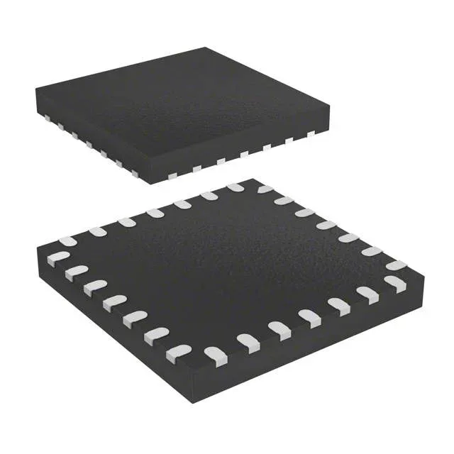
What sets it apart in this footprint is the integrated USB Type-C and Power Delivery controller — a feature normally requiring an external PHY and PD policy engine. For a board that needs a USB-C receptacle with PD negotiation, this single chip handles the MCU logic and the PD protocol stack, saving a separate controller IC and its associated firmware development.
64 MHz Cortex-M0+ — enough for most control loops
The Cortex-M0+ is a single-cycle I/O and interrupt engine, so the 64 MHz clock translates to responsive GPIO toggling and fast ADC trigger-to-read latency. If your application needs to run a PID loop at 20 kHz while managing USB PD negotiation and a UART debug stream, this core has the headroom without needing a Cortex-M4 or M7.
USB Type-C with Power Delivery — no external PD chip needed
The integrated USB Type-C and Power Delivery controller is the headline feature for this MCU. It handles the CC pin detection, PD message exchange, and voltage negotiation up to the 3.6 V supply limit. For a USB-C downstream-facing port or a dual-role port, this eliminates a dedicated PD controller (e.g., STUSB4500 or TPS65982) and its associated firmware. The BOM savings are real: one IC, one set of passives, and one firmware image instead of two.
There is no last-time-buy notification, no end-of-life schedule, and no successor part number to qualify. The ROHS3 compliance is current and covers all EU and UKCA regulatory requirements.
Analog integration: 12-bit ADC and DAC on-chip
Twelve 12-bit ADC channels and two 12-bit DAC channels are built into the MCU. For a mixed-signal control board — say, a sensor interface with analog output — this eliminates external ADC and DAC ICs. The ADC has a 0.5 µs conversion time at 12-bit resolution, fast enough for current sensing in a buck converter or position feedback in a brushless DC motor drive. The DAC can generate analog setpoints or waveform references without an external SPI/I2C DAC.
Package and thermal: 28-UFQFPN with exposed pad
For a PCB layout engineer, that pad needs a via array to the ground plane to pull heat out of the die. The junction-to-ambient thermal resistance is low enough that at 64 MHz with all peripherals active, the die stays well under the 85°C ambient limit — but the pad must be soldered, not left floating. The 26 I/O pins give enough headroom for a USB-C port, an SPI flash, a UART debug header, and a few sensor inputs without needing a larger package.