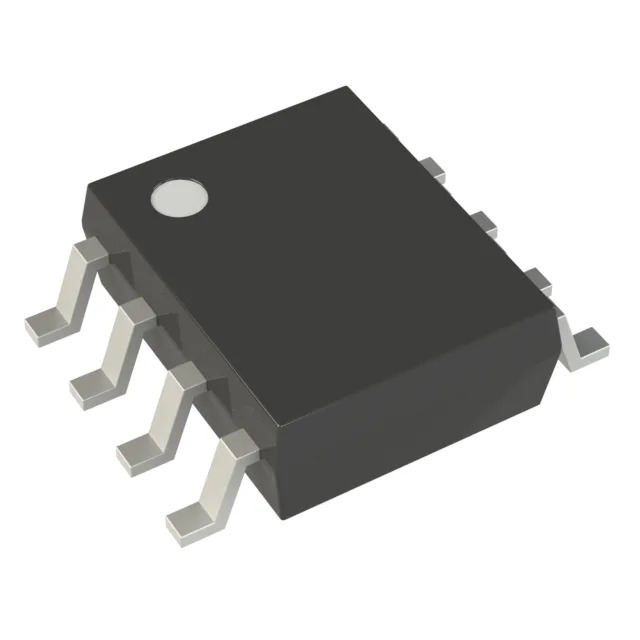
What this 8-pin MCU brings to a space-constrained BOM
Its six I/O lines and 8-SOIC footprint target single-function controllers where board area is the primary constraint — think sensor hubs, relay drivers, or simple motor commutation loops that don't need the pin count of a larger TQFP.
64 MHz on a Cortex-M0+ — enough for a single-loop controller
At 64 MHz the Cortex-M0+ delivers about 0.95 DMIPS/MHz, so you get roughly 60 DMIPS of integer throughput. That is enough for a single PID loop running at 10–20 kHz, a UART/SPI bridge, or a timed PWM waveform. The flash needs zero wait states up to 32 MHz; beyond that the prefetch buffer and ART accelerator keep single-cycle execution on linear code, so the headline 64 MHz is real for straight-line routines.
32 KB of program Flash and 8 KB of SRAM set a hard ceiling on firmware complexity. A bootloader, a main control loop, and a communication stack (I²C or UART) typically fit in 16–20 KB, leaving room for calibration tables or lookup curves. The 8 KB RAM handles a couple of moderate-sized buffers — for example a 1 KB UART FIFO and a 2 KB ADC sample ring — before running tight.
6 I/O in an 8-SOIC — counting the pins
The 8-SOIC package yields six usable GPIO pins after power and ground. That is enough for one serial interface (I²C or UART) plus two or three digital inputs or PWM outputs. If you need two serial ports or more than four general-purpose I/O, the same MCU core in a 16-pin or 20-pin package is the natural step-up. The 8-pin variant is the right choice when the entire system fits on a 10 mm × 10 mm board.
Peripherals on tap: ADC, timers, and serial interfaces
There is no USB or CAN controller on this die — the G031 series omits those blocks, so if you need USB connectivity you are looking at the STM32G071 or a different family. The ADC is real: eight external channels, 12-bit resolution, sampling rate around 1 MSps depending on clock configuration.
Industrial temperature range and active lifecycle
For dual-source resilience, the STM32G031K6 (20-pin TSSOP) is software-compatible but not pin-compatible; the 8-pin package has no pin-for-pin second source outside the STM32G0 family.