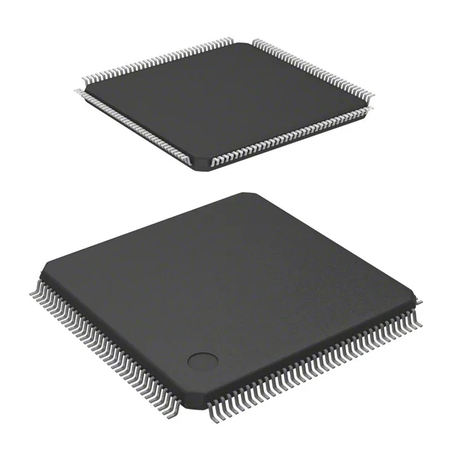
STM32F437ZIT7 — STM32F4 180MHz Cortex-M4 MCU, 2MB Flash, 144-LQFP
STMicroelectronics STM32F4 series ARM Cortex-M4 MCU; 180MHz, 2MB Flash, 256KB SRAM, 114 I/O, Ethernet, USB OTG, 24-ch 12-bit ADC, 2-ch 12-bit DAC, 144-LQFP (20×20mm), -40 to 105°C, 1.8–3.6V, tray.
Specifications
| Parameter | Value |
|---|---|
| Series | STM32F4 |
| Mounting | Surface Mount |
| Oscillator type | Internal |
| Program memory type | FLASH |
| Voltage - supply (Vcc (Vdd)) | 1.8V ~ 3.6V |
| Operating temperature | -40°C~105°C(TA) |
| Speed | 180MHz |
| Package | Tray |
| RAM size | 256K x 8 |
| Core size | 32-Bit Single-Core |
| Peripherals | Brown-out Detect/Reset, DMA, I²S, LCD, POR, PWM, WDT |
| Connectivity | CANbus, EBI/EMI, Ethernet, I²C, IrDA, LINbus, SPI, UART/USART, USB OTG |
| Number of i (O) | 114 |
| Core processor | ARM® Cortex®-M4 |
| Case | 144-LQFP |
| Data converters | A/D 24x12b; D/A 2x12b |
| Program memory size | 2MB (2M x 8) |
Frequently asked questions
Does the STM32F437ZIT7 need an external Ethernet PHY?
Yes. The Ethernet interface is a MAC only — the 144-LQFP package does not integrate a physical layer chip. Any Ethernet design using this MCU requires an external PHY, which adds BOM cost and layout area that should be accounted for at schematic review.
What is the thermal limit for continuous operation at full clock speed?
TA rating is -40 to 105°C. At 180MHz with the 24-channel ADC running full scan, thermal management under the exposed pad (144-LQFP, 20×20mm body) requires active consideration — the exposed pad thermal resistance path is part of the datasheet derating curve and should be verified against the specific board stackup and ambient conditions of the end application.