STMicroelectronics STM32F407IGH6 — Microcontrollers & Processors (MCU / MPU / DSP)

STM32F407IGH6 STM32F4 ARM Cortex-M4 MCU, 168MHz, 1MB Flash

MPNSTM32F407IGH6
Active

ST STM32F4 series, ARM Cortex-M4, 32-Bit Single-Core MCU, 168MHz, 1MB FLASH, 192K x 8 RAM, CANbus/Ethernet/USB OTG, 140 I/O, 201-UFBGA, -40°C~85°C.

$18.5800Ref. price · indicative, final on quote
Independent supplier — new & surplus stockAuthenticity-screened · ESD-safe packingListing updated Jul 2026

Specifications

STM32F407IGH6 specifications
ParameterValue
SeriesSTM32F4
MountingSurface Mount
Oscillator typeInternal
Program memory typeFLASH
Voltage - supply (Vcc (Vdd))1.8V ~ 3.6V
Operating temperature-40°C~85°C(TA)
Speed168MHz
PackageTray
RAM size192K x 8
Core size32-Bit Single-Core
PeripheralsBrown-out Detect/Reset, DMA, I²S, LCD, POR, PWM, WDT
ConnectivityCANbus, DCMI, EBI/EMI, Ethernet, I²C, IrDA, LINbus, SPI, UART/USART, USB OTG
Number of i (O)140
Core processorARM® Cortex®-M4
Case201-UFBGA
Data convertersA/D 24x12b; D/A 2x12b
Program memory size1MB (1M x 8)

Product details

168 MHz Cortex-M4 with DSP and FPU — the connectivity workhorse

The STM32F407IGH6 provides Ethernet MAC, two CAN 2.0B controllers, USB OTG HS/FS, DCMI, and EBI/EMI. 140 I/O pins are available on the 201-ball UFBGA.

1 MB Flash / 192 KB RAM — headroom for a full protocol stack

The 1 MB Flash (1M x 8) is organized with 4 KB and 128 KB sectors, which matters when you split firmware between a bootloader and application image. The 192 KB RAM includes 64 KB of CCM (core-coupled memory) that runs at full 168 MHz without wait states — put the interrupt vector table and real-time control loops there. The remaining 128 KB is split between SRAM1 and SRAM2 accessible by DMA and the Ethernet descriptor ring.

Industrial temperature range and active lifecycle

The lifecycle status is Active per ST's current product roster, which means no end-of-life notice is pending — it qualifies for new design-ins and long-term production commitments.

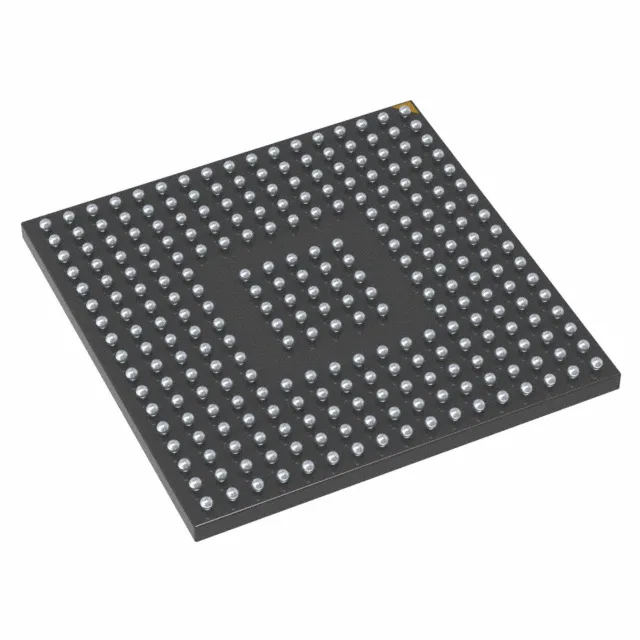
201-ball UFBGA — board layout and rework considerations

MSL 3 out of the bag — if the moisture barrier bag has been open longer than the floor-life window, a 24-hour bake at 125°C before reflow is mandatory to prevent popcorning. The 168 MHz core draws enough current that the LDO regulator on the die needs a clean 1.2 V rail from the internal regulator; bypass the Vcap pins with 2.2 µF and 100 nF as close to the balls as the via pattern allows.

Frequently asked questions

What is the difference between STM32F407IGH6 and STM32F407IGT6?

The two parts share the same die, Flash density (1 MB), RAM (192 KB), and peripheral set. The difference is the package: the IGH6 uses the 176+25 UFBGA (10x10 mm, 0.5 mm pitch), while the IGT6 uses a 176-pin LQFP (24x24 mm, 0.5 mm pitch). The UFBGA saves about 80% board area but requires a multi-layer PCB for fan-out; the LQFP is easier to hand-solder and inspect. Pin functions are identical, so a firmware image programmed for one runs on the other without changes.