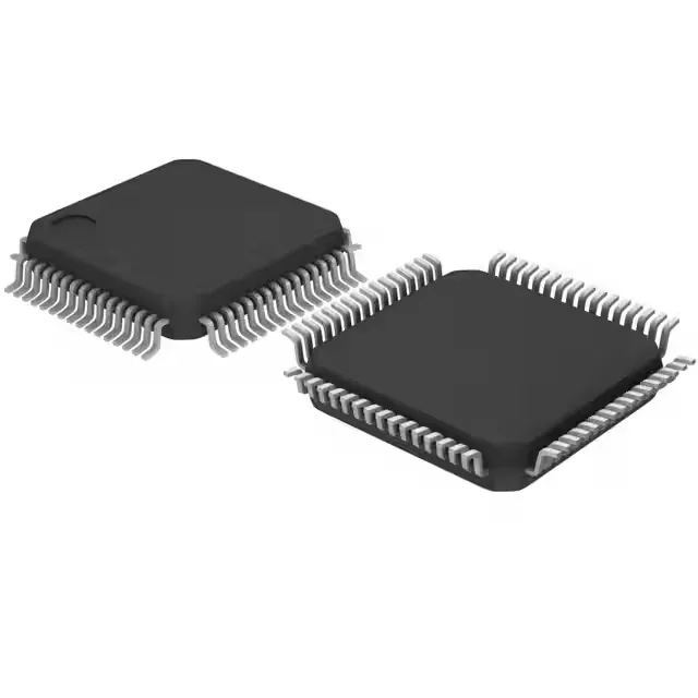
72 MHz Cortex-M4F with FPU — compute headroom for mixed-signal control
The single-precision floating-point unit (FPU) handles math-heavy tasks — FFT, PID compensation, sensor fusion — without an external DSP coprocessor. Program memory is 256 KB of Flash, backed by 8 KB of SRAM (organized as 8K x 8). The 1.65 V to 1.95 V supply range means this part runs from a 1.8 V rail; 3.3 V I/O needs level translation unless the peripheral is also 1.8 V tolerant. Typical applications include motor drives, industrial control loops, and field-instrumentation panels where the FPU and the peripheral set (CAN, SPI, I²C, UART, I²S) cover the interface mix.
The 256 KB Flash is organised as 256K x 8, which is enough for a real-time control stack plus a modest communications protocol (CANopen, Modbus) with room for a second bootloader slot if the application code stays under 128 KB. The 8 KB SRAM is tight — budget it carefully for DMA buffers and stack depth; if the control loop uses floating-point arrays, consider moving constants to Flash and using the RAM for scratch.
1.65 V to 1.95 V supply — design the rail before you route
The supply voltage (Vcc/Vdd) range is 1.65 V to 1.95 V, with a nominal 1.8 V target. This is a dedicated power rail — do not share it with a 3.3 V bus without a regulator. The 64-LQFP package (10x10 mm body) has 51 I/O available; the pinout is standard for the LQFP-64 footprint, so a layout from a sibling STM32F3 part in the same package should route with minor adjustments.