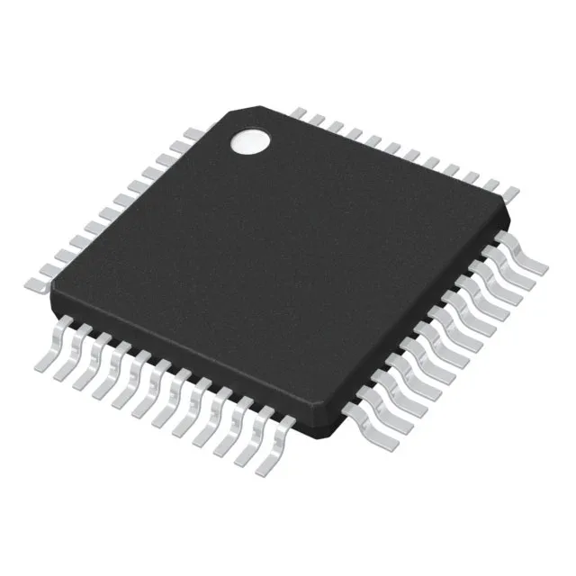
72 MHz core and 256 KB Flash — sizing the firmware and throughput budget
The 72 MHz clock rate is the ceiling for the Cortex-M4 core with zero-wait-state Flash access; above that the part would need wait states, but here the internal Flash controller is matched to the speed. For a typical control loop sampling an ADC at 1 MHz and running a PID filter with floating-point coefficients, the 72 MHz leaves enough margin to also handle a USB or CAN protocol stack without starving the control task. 256 KB of Flash is a practical size for a field-upgradable firmware image with a bootloader and one or two application slots. The 40K x 8 SRAM supports moderate data buffers — for example, a 1 KB USB endpoint buffer, a 2 KB CAN message queue, and a 16 KB DSP workspace still leave room for the stack and heap.
Peripheral set and connectivity — what is on-chip
The STM32F302CCT6TR integrates a DMA controller, I²S audio interface, power-on-reset (POR), PWM timers, and a watchdog timer — the usual STM32F3 complement for motor-control and audio applications. This set lets a single MCU handle a CANopen fieldbus, a USB virtual COM port for configuration, and a SPI link to an external FRAM or display — all without glue logic.