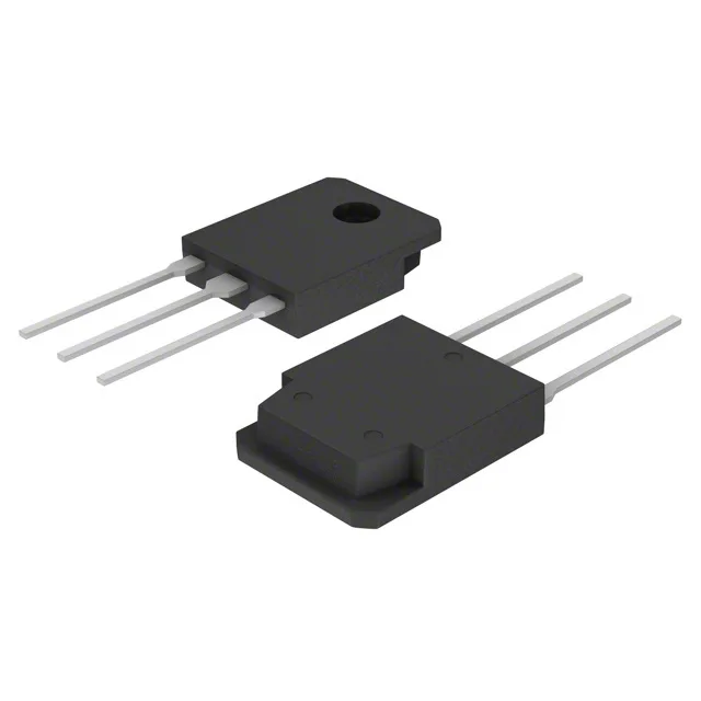
STMicroelectronics STGY40NC60VD

STGY40NC60VD IGBT 600V 80A PowerMESH™ TO-247

MPNSTGY40NC60VD
End of Life

STMicroelectronics PowerMESH™ IGBT, STGY40NC60VD, 600 V Collector-Emitter Breakdown, 80 A Collector, 260 W, TO-247-3 Through Hole, -55°C ~ 150°C.

$6.76Ref. price · indicative, final on quote
PackagingTO-247-3
StockContact for availability
MOQ1 pcs
  • 100% new & originalTraceable channels only — no refurbs, no pulls, no remarked parts.
  • Date & lot codes on quoteStated per line before you commit; label photos on request.
  • MSL-compliant ESD packingMoisture-sealed bags with indicator cards; reels photo-verified.
  • PayPal buyer protectionPay by T/T, PayPal or Payoneer — card payments covered end to end.

Specifications

STGY40NC60VD Technical Specifications
ParameterValue
SeriesPowerMESH™
Input typeStandard
Mounting typeThrough Hole
Voltage - collector emitter breakdown600 V
Current - collector (Ic)80 A
Power - max260 W
Operating temperature-55°C ~ 150°C (TJ)
PackageTube
Gate charge214 nC
CaseTO-247-3
Test condition390V, 40A, 3.3Ohm, 15V
Switching energy330µJ (on), 720µJ (off)
Td (on/off) @ 25°C43ns/140ns
Vce(on) (Max) @ vge, ic2.5V @ 15V, 40A
Reverse recovery time44 ns

Product details

600 V, 80 A — the power switch this BOM needs

The STGY40NC60VD is a 600 V, 80 A IGBT from ST's PowerMESH™ series, housed in a through-hole TO-247-3 package. It is designed for medium-frequency power switching where conduction losses and ruggedness matter more than raw switching speed — think motor drives, UPS inverters, welding machines, and induction heating stages that run in the 10–40 kHz range. The collector-emitter saturation voltage is 2.5 V typical at 15 V gate drive and 40 A collector current, which is the operating point the switching energy numbers are measured against: 330 µJ turn-on, 720 µJ turn-off at 390 V bus, 40 A, 3.3 Ω gate resistor.

Conduction loss and thermal budget

At 260 W maximum power dissipation in the TO-247 package, the thermal design must keep the junction below 150 °C. The 2.5 V Vce(on) at 40 A gives 100 W conduction loss at that current — derating is required above 25 °C case temperature, and the heatsink selection is the gating factor for continuous operation. The 214 nC total gate charge at 15 V means the gate driver needs to source and sink roughly 2 A peak to hit the 43 ns turn-on and 140 ns turn-off delay times. A standard 1 A gate driver will stretch those edges, increasing switching losses.

Switching performance at the test point

Tested at 390 V, 40 A with a 3.3 Ω gate resistor and 15 V gate drive, the device delivers 330 µJ turn-on and 720 µJ turn-off switching energy. The 44 ns reverse recovery time of the internal diode contributes to the turn-on loss budget. The 600 V breakdown voltage gives 20–30 % headroom on a 400 V DC bus — adequate for most single-phase and three-phase rectified mains applications. The 80 A collector rating is a peak pulse limit; continuous current is package- and temperature-limited.

Production status and compliance

ROHS3 compliant per. The TO-247-3 (MAX247™) through-hole package is a standard power footprint.

Frequently asked questions

Where can I buy STGY40NC60VD?

Buyers need to find authorized distributors with stock to purchase the part quickly.

What is the datasheet for STGY40NC60VD?

Design engineers need full specifications and electrical characteristics to validate fit.

What is the price of STGY40NC60VD?

Sourcing buyers need to compare pricing for BOM costing and budgeting.

What is the equivalent replacement for STGY40NC60VD?

Maintenance techs or brokers need substitutes when part is out of stock or obsolete.

Is STGY40NC60VD obsolete or EOL?

Brokers and buyers checking lifecycle status to ensure long-term availability.

What is the pinout of STGY40NC60VD?

Design engineers need pin configuration for PCB layout and compatibility.