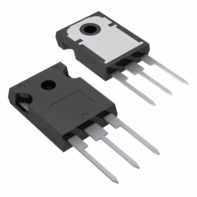
600 V / 60 A PowerMESH™ IGBT for hard-switching applications
It targets hard-switching topologies in motor drives, UPS, welding inverters, and induction heating where the DC bus sits at 390 V — the test condition listed in the datasheet.
Conduction and switching losses — the numbers that drive the heatsink
At Vge=15 V and Ic=20 A, the typical Vce(on) is 2.5 V — that 50 W conduction loss at 20 A is the baseline for heatsink sizing. The 100 nC total gate charge means a 1 A gate driver can switch this IGBT in about 100 ns, though the datasheet's td(on)/td(off) of 31 ns / 100 ns at 25°C gives the actual delay budget for dead-time calculation. Switching energy at the 390 V, 20 A, 3.3 Ω gate resistor test point is 220 µJ (turn-on) and 330 µJ (turn-off). The pulsed collector current rating of 100 A covers motor start inrush and capacitor precharge events, but the 60 A continuous ceiling is the steady-state limit for the bond wires and die attach.
The TO-247-3 through-hole package is a standard power footprint with a single mounting hole for a heatsink. The tube shipping quantity is the typical delivery format for this package.