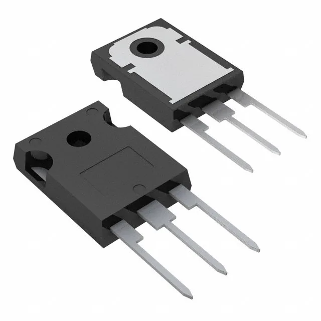
STMicroelectronics STGW20H60DF

STGW20H60DF IGBT, 600V 40A Trench Field Stop, TO-247

MPNSTGW20H60DF
End of Life

STMicroelectronics STGW20H60DF Trench Field Stop IGBT, 600 V collector-emitter breakdown, 40 A continuous collector, 167 W max power, TO-247-3 through-hole package, -55 to 175°C junction temperature.

$2.97Ref. price · indicative, final on quote
PackagingTO-247-3
RoHSROHS3 Compliant
Independent supplier — new & surplus stockAuthenticity-screened · ESD-safe packingListing updated Jul 2026

Specifications

STGW20H60DF specifications
ParameterValue
IGBT typeTrench Field Stop
Input typeStandard
MountingThrough Hole
Voltage - collector emitter breakdown600 V
Current - collector (Ic)40 A
Current - collector pulsed80 A
Power - max167 W
Operating temperature-55°C ~ 175°C (TJ)
PackageTube
Gate charge115 nC
CaseTO-247-3
Test condition400V, 20A, 10Ohm, 15V
Switching energy209µJ (on), 261µJ (off)
Td (on/off) @ 25°C42.5ns/177ns
Vce(on) (Max) @ vge, ic2V @ 15V, 20A
Reverse recovery time90 ns

Product details

600 V, 40 A Trench Field Stop IGBT in TO-247

It is designed for medium-power switching applications such as motor drives, inverters, and power supplies where low conduction and switching losses are required.

Conduction and switching losses at the test point

At the test condition of 400 V, 20 A with a 10 Ohm gate resistor and 15 V gate drive, the STGW20H60DF exhibits a Vce(on) of 2 V typical, setting a conduction loss floor of 40 W at that current. Switching energy measures 209 µJ during turn-on and 261 µJ during turn-off under the same conditions. Gate charge is 115 nC total, which determines the drive current needed from the gate driver to achieve the target switching frequency. The 42.5 ns turn-on delay and 177 ns turn-off delay at 25°C give a baseline for timing closure in the switching loop.

The 167 W maximum power dissipation sets the heatsink sizing target; actual dissipation depends on the switching frequency and load duty cycle. The reverse recovery time of the internal diode is 90 ns, relevant for hard-switching topologies where the diode's recovery charge contributes to turn-on loss in the complementary switch.

It is ROHS3 compliant.

Frequently asked questions

What is the gate charge of the STGW20H60DF?

Total gate charge is 115 nC, measured at the test condition of 400 V, 20 A with a 10 Ohm gate resistor and 15 V gate drive.