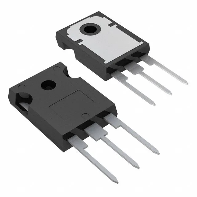
STMicroelectronics STGW19NC60HD

STGW19NC60HD IGBT 600V 42A PowerMESH™ TO-247

MPNSTGW19NC60HD
End of Life

STMicroelectronics PowerMESH™ IGBT, STGW19NC60HD, 600V Vces, 42A Ic, 140W max, 53nC gate charge, TO-247-3 through-hole package, -55 to 150°C junction temperature.

$3.11Ref. price · indicative, final on quote
PackagingTO-247-3
RoHSROHS3 Compliant
SeriesPowerMESH™
Independent supplier — new & surplus stockAuthenticity-screened · ESD-safe packingListing updated Jul 2026

Specifications

STGW19NC60HD specifications
ParameterValue
SeriesPowerMESH™
Input typeStandard
MountingThrough Hole
Voltage - collector emitter breakdown600 V
Current - collector (Ic)42 A
Current - collector pulsed60 A
Power - max140 W
Operating temperature-55°C ~ 150°C (TJ)
PackageTube
Gate charge53 nC
CaseTO-247-3
Test condition390V, 12A, 10Ohm, 15V
Switching energy85µJ (on), 189µJ (off)
Td (on/off) @ 25°C25ns/97ns
Vce(on) (Max) @ vge, ic2.5V @ 15V, 12A
Reverse recovery time31 ns

Product details

600 V, 42 A — the switching envelope

The STGW19NC60HD is a 600 V, 42 A IGBT from ST's PowerMESH™ series, rated for 140 W maximum power dissipation in a TO-247-3 through-hole package. The 600 V collector-emitter breakdown voltage and 42 A continuous collector current define its primary application space: motor drives, UPS inverters, welding machines, and induction heating circuits where the DC bus sits at 300–400 V and the load draws tens of amps.

Total gate charge is 53 nC, tested at 390 V, 12 A, 10 Ω gate resistor, 15 V gate drive — a realistic hard-switching condition for a 600 V IGBT in a 400 V bus inverter leg. Turn-on delay is 25 ns, turn-off delay 97 ns at 25 °C. Switching energy numbers — 85 µJ on, 189 µJ off — let you calculate per-cycle loss directly: at 20 kHz switching, the combined 274 µJ per transition works out to about 5.5 W switching loss, before adding conduction loss from Vce(on). The 53 nC gate charge means a standard 1–2 A gate driver IC can charge and discharge the gate within the dead-time budget at typical switching frequencies.

Thermal and temperature rating — fit for harsh environments

The 140 W power dissipation assumes the TO-247 case is properly heatsunk — the long-lead variant (TO-247 Long Leads) gives clearance for thick insulating pads or direct mounting to a heatsink. Reverse recovery time of the internal diode is 31 ns, relevant in half-bridge topologies where the freewheeling diode must recover fast enough to avoid shoot-through.

ROHS3 compliant.

Frequently asked questions

What are the gate charge and switching energy specs of the STGW19NC60HD?

Total gate charge is 53 nC under test conditions of 390 V, 12 A, 10 Ω gate resistor, 15 V gate drive. Turn-on switching energy is 85 µJ, turn-off is 189 µJ. Turn-on delay is 25 ns, turn-off delay 97 ns at 25 °C junction temperature.

What is the closest pin-compatible alternative to the STGW19NC60HD?

Within the 600 V PowerMESH™ family, other parts share the same TO-247-3 footprint, but gate charge, switching energy, and current rating differ — verify the drive circuit and loss budget before substituting.