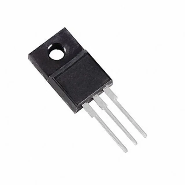
600 V, 14 A Trench Field Stop IGBT in TO-220FP
The STGF7H60DF is a 600 V, 14 A Trench Field Stop IGBT from STMicroelectronics in a TO-220FP (full-pack) through-hole package. It targets hard-switching applications such as motor drives, power inverters, and PFC stages where low saturation voltage and fast switching are required.
Switching losses and gate drive budget
At the test condition of 400 V, 7 A, 47 Ω gate resistor, and 15 V gate drive, the part switches 99 µJ on and 100 µJ off. The 46 nC total gate charge means the gate driver must source 46 nC per switching cycle; at 20 kHz switching, that is an average gate current of about 0.9 mA, easily met by most standard gate-drive ICs. Turn-on delay is 30 ns, turn-off delay 160 ns at 25 °C junction. The 136 ns reverse recovery time of the internal diode (co-packaged) helps limit turn-on losses in hard-switching topologies.
Thermal and package considerations
Maximum power dissipation is 24 W. The TO-220FP full-pack package has a fully isolated tab — no insulating pad or washer needed between the device and heatsink, which simplifies assembly and reduces thermal resistance in the mounting stack. The 1.95 V typical Vce(on) at 15 V gate and 7 A collector current sets the conduction loss floor. At 7 A, that is about 13.7 W conduction loss — well within the 24 W package limit, but thermal design must account for the heatsink's ability to keep junction temperature below 175 °C at the target ambient.