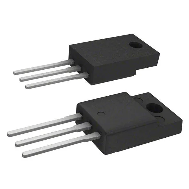
STMicroelectronics STGF10NC60KD

STGF10NC60KD IGBT 600V 9A TO-220FP PowerMESH™

MPNSTGF10NC60KD
End of Life

STMicroelectronics PowerMESH™ IGBT, STGF10NC60KD, 600 Vce, 9 A Ic, 25 W max, TO-220-3 Full Pack through-hole package, 19 nC gate charge, -55 to 150 °C junction temperature.

$1.62Ref. price · indicative, final on quote
PackagingTO-220-3 Full Pack
RoHSROHS3 Compliant
SeriesPowerMESH™
Independent supplier — new & surplus stockAuthenticity-screened · ESD-safe packingListing updated Jul 2026

Specifications

STGF10NC60KD specifications
ParameterValue
SeriesPowerMESH™
Input typeStandard
MountingThrough Hole
Voltage - collector emitter breakdown600 V
Current - collector (Ic)9 A
Current - collector pulsed30 A
Power - max25 W
Operating temperature-55°C ~ 150°C (TJ)
PackageTube
Gate charge19 nC
CaseTO-220-3 Full Pack
Test condition390V, 5A, 10Ohm, 15V
Switching energy55µJ (on), 85µJ (off)
Td (on/off) @ 25°C17ns/72ns
Vce(on) (Max) @ vge, ic2.5V @ 15V, 5A
Reverse recovery time22 ns

Product details

600V, 9A PowerMESH™ IGBT in TO-220FP

The STGF10NC60KD is a 600 V, 9 A IGBT from STMicroelectronics' PowerMESH™ series, housed in a TO-220 Full Pack (TO-220FP) through-hole package.

Conduction and switching numbers that matter

The 600 V collector-emitter breakdown gives enough headroom for 230 VAC rectified bus (≈325 VDC) or 380 VDC rail in a motor drive. Total gate charge is 19 nC, low enough that a simple bootstrap gate-drive IC can switch it at moderate frequency without a separate isolated supply. Switching losses at the 390 V, 5 A, 10 Ω gate resistor test condition are 55 µJ turn-on and 85 µJ turn-off — figures that let you estimate junction temperature rise before you pick a heatsink.

Pulsed current and thermal envelope

Pulsed collector current is rated 30 A — useful for capacitor charging, inrush limiting, or short-circuit-withstand checks. The 25 W maximum power dissipation in the TO-220FP package means the heatsink is not optional above a few watts; the full-pack case has higher thermal resistance than a standard TO-220 with an exposed metal tab. The 22 ns reverse recovery time of the internal co-pack diode matters when the IGBT commutates into an inductive load — shorter trr reduces the dead-time needed in the complementary switch.

ROHS3 compliant.

Frequently asked questions

What is the maximum collector current (Ic) of STGF10NC60KD?

Continuous collector current (Ic) is rated 9 A. Pulsed collector current (Icm) is rated 30 A.

What is the Vce(on) of STGF10NC60KD?

Vce(on) is 2.5 V maximum at Vge = 15 V and Ic = 5 A.

What is the gate charge of STGF10NC60KD?

Total gate charge is 19 nC.

What is the switching energy of STGF10NC60KD?

At the test condition of 390 V, 5 A, 10 Ω gate resistor, 15 V gate drive: turn-on switching energy is 55 µJ, turn-off is 85 µJ.