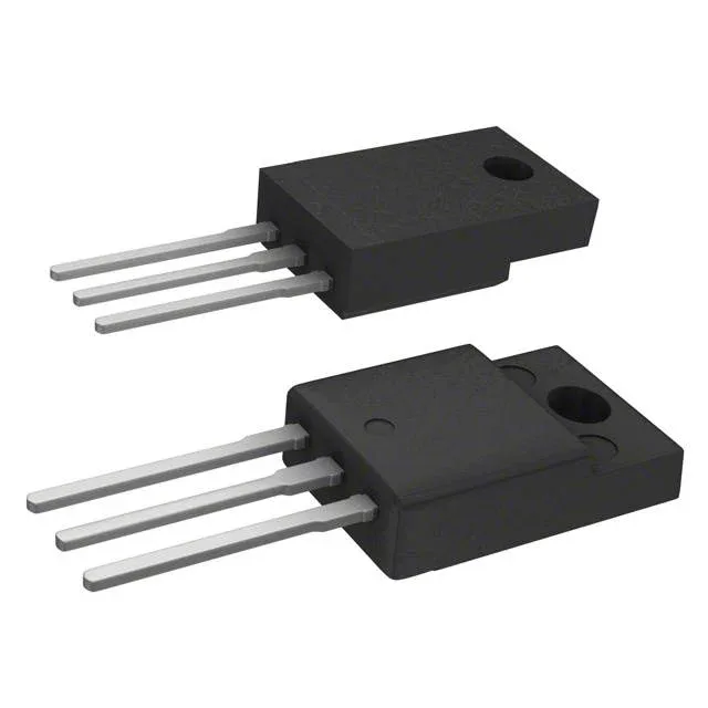
STMicroelectronics STGF10NB60SD

STGF10NB60SD IGBT, 600 V 23 A, TO-220FP, PowerMESH™

MPNSTGF10NB60SD
End of Life

STMicroelectronics PowerMESH™ IGBT, STGF10NB60SD, 600 V collector-emitter breakdown, 23 A continuous collector, 25 W max, TO-220-3 Full Pack through-hole, -55°C to 150°C junction.

$2.26Ref. price · indicative, final on quote
PackagingTO-220-3 Full Pack
RoHSROHS3 Compliant
SeriesPowerMESH™
Independent supplier — new & surplus stockAuthenticity-screened · ESD-safe packingListing updated Jul 2026

Specifications

STGF10NB60SD specifications
ParameterValue
SeriesPowerMESH™
Input typeStandard
MountingThrough Hole
Voltage - collector emitter breakdown600 V
Current - collector (Ic)23 A
Current - collector pulsed80 A
Power - max25 W
Operating temperature-55°C ~ 150°C (TJ)
PackageTube
Gate charge33 nC
CaseTO-220-3 Full Pack
Test condition480V, 10A, 1kOhm, 15V
Switching energy600µJ (on), 5mJ (off)
Td (on/off) @ 25°C700ns/1.2µs
Vce(on) (Max) @ vge, ic1.75V @ 15V, 10A
Reverse recovery time37 ns

Product details

600 V, 23 A — where this IGBT sits in the kit

The STGF10NB60SD is an STMicroelectronics PowerMESH™ IGBT rated for 600 V collector-emitter breakdown and 23 A continuous collector current, in a TO-220FP full-pack through-hole package. It is a standard-input N-channel device built for hard-switched power stages — motor drives, UPS inverters, PFC boost stages — where the 600 V blocking voltage gives margin on a 400 V DC bus.

Switching losses — the off-energy is the number to watch

Under the test condition of 480 V, 10 A, 1 kOhm gate resistor, and 15 V gate drive, the turn-on switching energy is 600 µJ and the turn-off energy is 5 mJ. The off-energy dominates by nearly an order of magnitude, which means this part runs hottest during the turn-off edge — a snubber or a slower gate-drive turn-off can shift some of that loss, but the thermal design should budget for the 5 mJ per pulse at the target switching frequency. Turn-on delay is 700 ns, turn-off delay is 1.2 µs at 25 °C junction.

On-state voltage and gate drive

Vce(on) is 1.75 V maximum at 15 V gate drive and 10 A collector current — a typical conduction loss for a 600 V trench IGBT in this current class. The total gate charge is 33 nC, so a standard MCU GPIO through a 1 kOhm resistor will switch it, but the 700 ns/1.2 µs delays mean the gate driver should source at least 0.5 A peak to keep the switching edges clean.

Package — TO-220FP full-pack, no heatsink isolation worries

The TO-220FP full-pack moulding isolates the tab electrically — no insulating pad or washer needed when bolting to a grounded heatsink. The through-hole mounting is field-serviceable with a standard soldering iron; the three leads are spaced at 2.54 mm pitch, easy to probe and replace on site.

Frequently asked questions

Does the STGF10NB60SD fit a TO-220FP footprint?

Yes. The supplier device package is TO-220FP, which is the full-pack variant of the standard TO-220 outline. The three leads are on 2.54 mm pitch and the mounting hole pattern is identical to a standard TO-220.

What is the difference between STGF10NB60SD and STGF10NB60S?

The evidence does not carry a direct comparison entry for the STGF10NB60S variant. For a pin-compatible alternative within the same PowerMESH™ family, confirm the specific suffix differences against the STMicroelectronics datasheet — the 'D' suffix typically denotes a different diode or switching speed grade, but this is not confirmed in the on-record data.