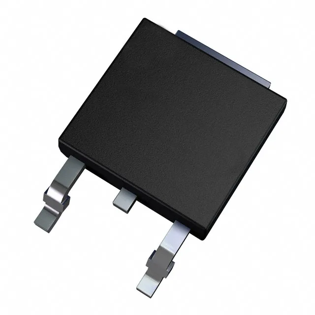
600 V, 15 A — what this IGBT handles
The STGD7NB60ST4 is an STMicroelectronics PowerMESH™ IGBT rated at 600 V collector-emitter breakdown and 15 A continuous collector current, with a 60 A pulsed capability. That voltage and current class puts it squarely in the 200–400 VDC bus range for motor drives, UPS inverters, and induction heating stages — not the 1200 V traction tier, but well above the 300 V ceiling of a standard boost converter.
Switching losses set the frequency ceiling
The turn-off switching energy is 3.5 mJ at the test condition of 480 V, 7 A, 1 kOhm gate resistor, 15 V gate drive. For a hard-switched application, that 3.5 mJ per cycle times the switching frequency gives the switching loss component of the junction temperature budget. At 10 kHz the switching loss alone is 35 W — already over the 55 W package limit — so this part is realistically a 2–8 kHz switch in a typical motor drive or welder, not a 20+ kHz PFC stage. Gate charge is 33 nC, which is modest for a 15 A IGBT. A standard gate driver with 1 A peak output charges the gate in about 33 ns, so the turn-on delay is dominated by the driver's sink current and the external gate resistor, not the part itself.
DPAK — field-replaceable if you have the kit
The DPAK (TO-252) surface-mount package is a common three-lead tabbed part. On a site visit with a hot-air station and some solder wick, it is a 5-minute swap — the tab is the collector, the two outer pins are gate and emitter. The part is marked with the full order code, so orientation is clear even without a magnifier. No lab bench required; just a steady hand and a reflow profile that does not cook the adjacent parts.