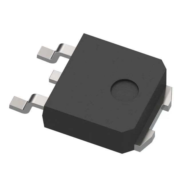
Automotive IGBT for engine-bay power stages
It blocks 435 V collector-emitter and conducts 25 A continuous, with the junction rated to 175 °C — the temperature grade that matches engine-bay thermal cycling without headroom games.
Total gate charge is 26 nC, measured under the test condition 300 V, 10 A, 1 kOhm gate resistor, 5 V gate drive. The 1.1 µs turn-on and 4.6 µs turn-off delay times at 25 °C mean the gate driver sees moderate capacitive load — a standard automotive gate-driver IC with 2 A peak output handles the switching without external booster stages.
On-state voltage and saturation margin
Vce(on) max is 1.25 V at 4 V gate drive, 6 A collector current. That 1.25 V saturation voltage at a 6 A test point is the conduction loss floor per die; at full 25 A the Vce(on) rises with temperature, so the 125 W package power limit sets the real-world duty-cycle ceiling in a 85 °C ambient environment.
Pulsed current and SOA boundary
Pulsed collector current rating is 50 A — double the continuous 25 A — for short-duration events such as inrush or load dump. The 435 V breakdown gives enough headroom for a nominal 400 V DC bus with the usual 20 % margin for switching overshoot.
The automotive qualification (AEC-Q101) means PPAP documentation is available through the manufacturer channel.