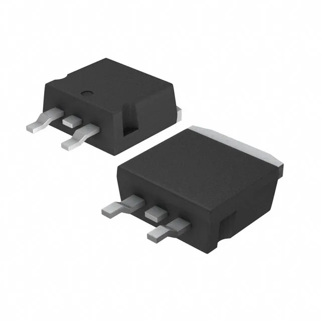
600 V, 35 A — the switching backbone for motor drives and PFC
The STGB19NC60KDT4 is a 600 V, 35 A IGBT from ST's PowerMESH™ series, built for hard-switching topologies like motor drives, power-factor correction, and induction-heating converters. The 600 V collector-emitter breakdown gives headroom for 230 VAC rectified rails (≈ 325 VDC) plus switching overshoot; the 35 A continuous collector rating handles a 1.5 kW motor drive with margin before paralleling. The 125 W power dissipation ceiling in the D2PAK surface-mount package means the board's copper area and airflow set the real thermal limit — expect to budget a 2 oz copper pour under the tab for continuous 15 A operation.
Switching losses and dead-time budgeting
Under the test condition of 480 V, 12 A, 10 Ω gate resistor, and 15 V gate drive, the turn-on switching energy is 165 µJ and turn-off is 255 µJ. At a 20 kHz switching frequency those losses sum to about 8.4 W — within the 125 W package limit but requiring a heatsink or forced airflow. The 30 ns turn-on delay and 105 ns turn-off delay at 25 °C let you set dead-time below 200 ns in a complementary-leg inverter. The 55 nC total gate charge is modest — a standard 1 A gate-driver IC can switch this IGBT at 50 kHz without excessive drive power.
D2PAK rework and thermal handling
The D2PAK (TO-263-3) package has a large exposed copper tab that must be soldered to the PCB pad for both electrical connection and thermal conduction. Will it survive the hot air? Yes — the tab's thermal mass is manageable with a 150 °C preheat and a focused nozzle; the risk is lifting the tab pad if the board has a thick ground plane. The 150 °C junction rating gives margin for reflow peaks as long as the board bake cycle is followed for moisture-sensitive devices.