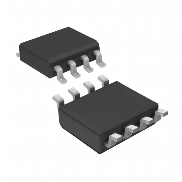
Isolated gate driver for SiC and IGBT switching
The STMicroelectronics STGAP2SMTR is a single-channel isolated gate driver using magnetic coupling to deliver 1700 VDC of galvanic isolation between the input logic and the output power stage. It provides 4 A peak source and sink current, making it suitable for driving large IGBTs and SiC MOSFETs in motor drives, inverters, and power supplies.
1700 VDC isolation — what it enables
The 1700 VDC isolation rating is the standout parameter. It allows the STGAP2SMTR to sit on the secondary side of a high-voltage DC bus — common in 3-phase inverter rails up to 1000 VDC — without needing an external isolated DC-DC for the gate-drive supply. The magnetic-coupling technology meets reinforced isolation requirements for motor-drive and solar-inverter designs where safety separation between the controller and power stage is mandatory.
4 A peak drive and switching speed
The output supply range of 9.6 V to 26 V gives flexibility to match the gate-drive voltage to the power device's requirements — 15 V for standard IGBTs, 18 V to 20 V for SiC MOSFETs. The 100 ns maximum propagation delay on both edges is consistent enough that dead-time can be set tightly without excessive margin, though the 20 ns pulse-width distortion should be factored into the timing budget.
CMTI and noise immunity
Common-mode transient immunity is specified at a minimum of 100 V/ns. In a hard-switching inverter, the voltage on the power-stage reference can slew at several tens of V/ns; the STGAP2SMTR's CMTI ensures the output state does not glitch or latch up during these events, which is critical to preventing shoot-through faults.
Active lifecycle — no near-term obsolescence
It can be designed into new production without concern for last-time-buy windows. For dual-sourcing resilience, the pin-compatible STGAP2SICSC is a functional second source with similar 4 A output and 100 V/ns CMTI, though its propagation delay is slightly tighter at 90 ns typical.