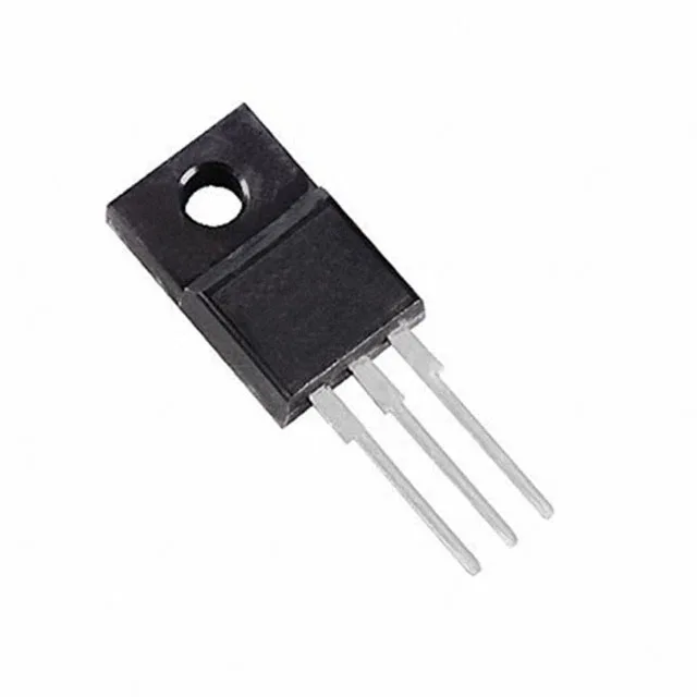
600 V N-channel in a full-pack isolator
On-resistance and gate charge — the switching trade-off
Rds(on) is 1.4 Ohm maximum at 1.85 A drain current with 10 V gate drive. The 20 W power dissipation limit sets the thermal ceiling for conduction and switching losses combined. Total gate charge Qg is 4.5 nC at Vgs=10 V, and input capacitance Ciss is 165 pF at Vds=100 V. These are low numbers for a 600 V device — the gate driver sees a light capacitive load, so switching transition times stay short even with a modest drive current. In a 100 kHz flyback, the gate-drive power required is roughly Qg × Vgs × fsw = 4.5 nC × 10 V × 100 kHz = 4.5 mW, negligible in the system budget.
Package thermal reality — the full-pack trade-off
The TO-220FP (supplier device package TO-220FP) has a fully isolated plastic tab — no metal backside, no mounting hole. For continuous operation above a few watts, a heatsink with good airflow or forced convection is necessary. The through-hole mounting suits boards where mechanical retention matters — the leads take the strain, unlike a surface-mount part that relies on solder fillets.
It is ROHS3 compliant.