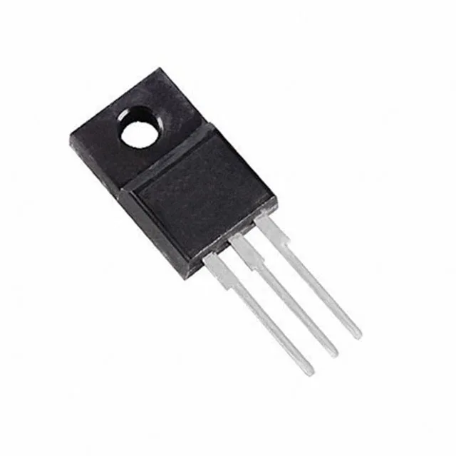
The device is packaged in a TO-220-3 Full Pack (TO-220FP), which provides an isolated mounting surface — no insulating washer needed between the tab and the heatsink.
110 mΩ at 14.5 A — conduction loss anchor
At 28 A the on-resistance will be higher (the 110 mOhm figure is tested at 14.5 A), so the designer should budget for a 20–30 % increase when sizing the heatsink. The 35 W maximum power dissipation in the TO-220FP is the package-level constraint — thermal resistance junction-to-case is higher than a standard TO-220 because of the full-pack isolation, so the junction temperature rise under continuous 28 A operation needs careful verification.
Gate charge and input capacitance — switching speed budget
These numbers define the gate-drive power requirement and the switching transition time. A 70 nC gate charge is moderate — a typical gate-driver IC with 1 A peak current can switch the FET in the 50–100 ns range, but the 2590 pF Ciss means the driver must supply enough instantaneous current to charge that capacitance quickly. For hard-switching topologies above 100 kHz, the gate-drive loop inductance and driver output resistance become critical to avoid turn-on/turn-off losses.
STMicroelectronics lists the STF34N65M5 as Active. For new designs this removes the obsolescence risk that haunts older MOSFET series.