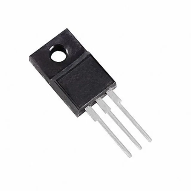
600 V, 18 A — sizing the STF25N60M2-EP for your power stage
That saves a BOM line and a manual assembly step. At 18 A the Rds(on) will be higher — the datasheet's normalised curve shows the typical factor — so budget for that when you size the heatsink. The 30 W power dissipation ceiling at the case is the hard thermal limit; your actual dissipation will be lower once you derate for your operating case temperature.
Gate charge and switching — what 29 nC means for your driver
That is low for a 600 V, 18 A MOSFET — the MDmesh structure keeps the Qg down. A typical gate driver with 1 A peak source/sink can switch this device in under 30 ns, which keeps switching losses manageable even at 100 kHz. The gate threshold voltage maximum is 4.75 V at 250 µA drain current. That means you need a clean 10 V gate drive to guarantee the lowest Rds(on); a 5 V logic-level drive will not fully enhance this device. The absolute maximum gate-source rating is ±25 V, so a 12 V or 15 V gate drive rail is safe as long as you stay under that ceiling.
Temperature range and where this part lives
The 30 W power limit at the case is the reference; derate linearly above 25°C case temperature.
The MDmesh M2-EP series is ST's current-generation high-voltage MOSFET platform, so second-source options are limited to other vendors' equivalent 600 V, 18 A, TO-220FP parts — no direct pin-compatible ST alternate is listed.