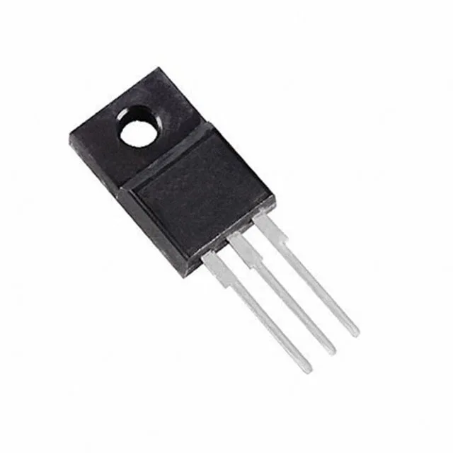
600 V N-channel with a full-pack body — why the package matters
That saves a BOM line and eliminates the assembly step of placing a silicone pad or mica washer.
Conduction loss and gate drive budget
The typical value from the description is 0.255 Ohm — the 280 mOhm max is the number to use for worst-case thermal calculations. Gate charge is 21.5 nC at 10 V, which keeps the gate-drive power low in a 100 kHz switching regulator; a typical 1 A gate driver charges the gate in about 22 ns. Input capacitance is 791 pF at 100 V drain-source — this is the Ciss that the driver sees during the Miller plateau. The low capacitance relative to the 600 V / 13 A rating is the MDmesh II Plus design target: fast switching with reduced crossover losses in hard-switched topologies.
Thermal and temperature envelope
The 25 W ceiling means this part is not for a multi-kilowatt inverter stage — it fits auxiliary supplies, PFC stages up to about 300 W, and flyback converters where the full-pack isolation simplifies the mechanical design. The 150 °C Tj max is standard for industrial SMPS designs that see sustained load.