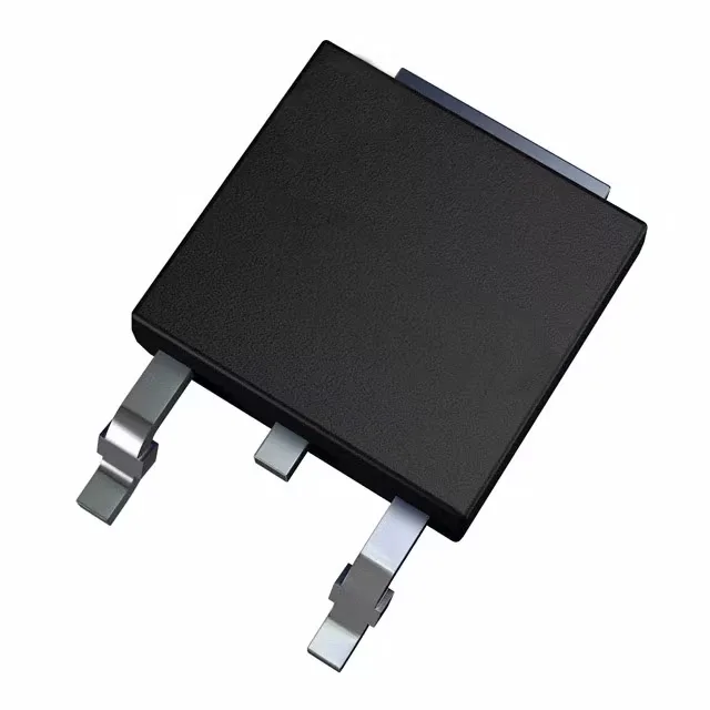
This is a high-voltage switching device built on standard MOSFET (Metal Oxide) technology, intended for applications where the primary design constraint is blocking voltage rather than ultra-low on-resistance. The 620 V Vdss puts it squarely in the offline power supply and LED lighting driver space, where the rectified mains rail (typically 310 V to 400 V DC) needs a switch with comfortable derating margin. The 5 A continuous rating at the case means the actual usable current in a real PCB layout will be lower — the 70 W maximum power dissipation (Tc) is the real thermal ceiling, and the DPAK's tab must be soldered to a sufficient copper area or heatsink to pull that heat out.
On-resistance and gate drive — sizing the gate driver and estimating conduction loss
The STDLED625 specifies a maximum Rds(on) of 1.6 Ohm at 2.1 A drain current with 10 V gate drive. The gate threshold voltage (Vgs(th)) has a maximum of 4.5 V at 50 µA, which means the device begins to turn on around 3-4 V, but the channel resistance stays high until the gate is driven to the full 10 V. For a BOM engineer, this means the gate driver circuit needs to supply at least 10 V, typically from a bootstrap or charge-pump stage in a half-bridge, or from a dedicated 10-12 V rail in a single-ended flyback or buck converter.
Package and thermal reality — the DPAK tab is your heatsink
The STDLED625 comes in the TO-252-3 DPAK (DPak, 2 Leads + Tab, SC-63) surface-mount package, supplied on Tape & Reel. This is a standard power package where the center tab is the drain connection and the primary thermal path. The 70 W maximum power dissipation at case temperature assumes the tab is held at 25°C — in practice, the junction-to-ambient thermal resistance of a DPAK on a standard FR4 board with minimal copper is around 60-80 °C/W, limiting dissipation to 1-2 W without a heatsink. For the full 5 A rating, the tab needs to be soldered to a large copper pour on the PCB, or bolted to an external heatsink through the tab hole.