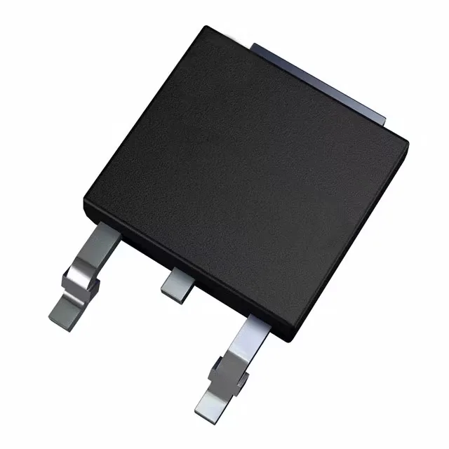
STMicroelectronics STD96N3LLH6 — Discrete Semiconductors

STD96N3LLH6 N-Channel MOSFET, 30 V, 4.2 mΩ, DPAK

MPNSTD96N3LLH6
Active

STMicroelectronics DeepGATE™, STripFET™ VI series, N-Channel MOSFET, 30 V drain-source, 4.2 mOhm Rds(on) at 10 V gate drive, 80 A continuous drain, DPAK surface-mount package.

$1.3400Ref. price · indicative, final on quote
Independent supplier — new & surplus stockAuthenticity-screened · ESD-safe packingListing updated Aug 2026

Specifications

STD96N3LLH6 specifications
ParameterValue
SeriesDeepGATE™, STripFET™ VI
FET typeN-Channel
MountingSurface Mount
Drain to source voltage30 V
Drive voltage (Max rds on, min rds on)5.5V, 10V
Current - continuous drain (Id) @ 25°C80A (Tc)
Power dissipation70W (Tc)
Operating temperature175°C(TJ)
PackageTape & Reel (TR); Cut Tape (CT)
Vgs±20V
TechnologyMOSFET (Metal Oxide)
CaseTO-252-3, DPak (2 Leads + Tab), SC-63
Vgs(th) (Max) @ id2.5V @ 250µA
Rds on (Max) @ id, vgs4.2mOhm @ 40A, 10V
Gate charge (Qg) (Max) @ vgs20 nC @ 4.5 V
Input capacitance (Ciss) (Max) @ vds2200 pF @ 25 V

Product details

30 V, 4.2 mΩ — what the headline numbers mean for your switching node

The STD96N3LLH6: It is rated for a 30 V drain-source voltage and delivers a maximum Rds(on) of 4.2 mΩ at 10 V gate drive with 40 A drain current.

Gate charge and drive voltage — the switching-speed lever

The drive voltage range spans 5.5 V to 10 V for the best Rds(on); at 4.5 V the on-resistance roughly doubles from the 10 V value, so a 5 V logic supply still works but you lose some conduction efficiency. The input capacitance of 2200 pF at 25 V drain-source means the gate-drive loop needs a clean layout — a 10 Ω series resistor and a Schottky catch diode on the gate trace are cheap insurance against ringing.

Thermal budget — 70 W dissipation in a DPAK

Maximum power dissipation is 70 W at the case, but that number assumes an infinite heatsink. In a real board with 1 oz copper and no forced air, the junction-to-ambient thermal resistance of a DPAK lands around 50–60 °C/W, so the practical continuous dissipation is closer to 2–3 W before the junction hits 175 °C. The 175 °C junction rating gives margin for short overloads, but sustained high-current operation needs a copper pour on the drain tab and preferably a thermal via array to an inner plane.

Frequently asked questions

What is the Rds(on) of STD96N3LLH6?

At 4.5 V drive the on-resistance is higher — the datasheet typical curve shows roughly double the 10 V value.