The SuperFREDmesh™ family uses a fast-recovery body diode and optimized gate charge (11.8 nC at 10 V) to reduce switching losses in hard-switched topologies.
If your design allows a pin-compatible alternative, the closest functional match would be another 600 V N-channel DPAK MOSFET in the same current class — but no direct drop-in replacement is documented by ST. Plan for a qualification cycle if substituting.
The 3.6 Ω on-resistance is specified at 1.2 A drain current with 10 V gate drive. The drive voltage entry lists 10 V as the recommended level for minimum on-resistance. If your gate driver supplies only 5 V, expect roughly double the Rds(on) and higher conduction loss.
DPAK rework and thermal layout
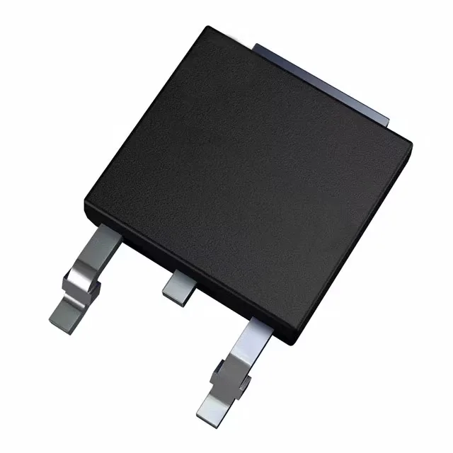
The TO-252 DPAK package has three leads plus a large exposed tab. The tab solder area on the PCB should have a solid copper pour and at least four thermal vias to the inner ground plane. Without that via stitch, the 45 W dissipation rating is theoretical; in practice the junction will exceed 150 °C above 1.5 A continuous in still air.