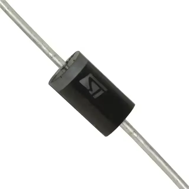
1500 W surge clamp for 48 V rails
It delivers 1500 W of peak pulse power in a standard 10/1000 µs waveform, with a reverse standoff voltage of 47.8 V and a minimum breakdown of 53.2 V. When the surge current hits, the clamping voltage holds at 100 V maximum, shunting up to 100 A (8/20 µs) away from the protected circuit. The DO-201AA axial-lead package suits through-hole mounting on boards where a high-energy pulse needs a rugged, solderable joint.
The 47.8 V reverse standoff voltage means this TVS does not conduct at normal 48 V bus levels, so it adds no leakage on a powered rail. The 53.2 V minimum breakdown sets the threshold where clamping begins — a transient that exceeds this voltage triggers the avalanche. The 100 V clamping maximum at peak pulse current defines the worst-case voltage the downstream components must survive; if the load's absolute maximum rating is below 100 V, this part provides a hard clamp. The 1500 W rating (10/1000 µs) tells you the energy-handling capacity for a single surge event — enough for a lightning-induced transient on an outdoor telecom line or an inductive kick from a motor drive. The bidirectional construction (single device) protects against both positive and negative spikes, saving a diode bridge in AC-coupled or bipolar signal paths.
The DO-201AA (DO-27) axial-lead package is a through-hole form factor with a body diameter sized for the 1500 W dissipation. It solders into a 1.1 mm diameter hole on the PCB; the leads are tin-plated and compatible with standard wave-solder profiles. No special footprint beyond the two-hole pattern is needed, and the part's MSL is not listed — but given the axial construction and plated leads, moisture sensitivity is not a concern for this package class. The leads are long enough for hand-replacement in repair scenarios, though the thermal mass means a soldering iron with a wide tip and good heat transfer is recommended.