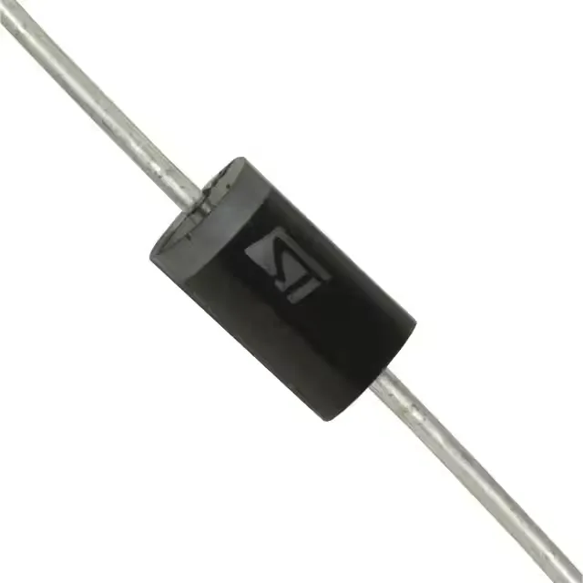
Its 1500W peak pulse power rating (10/1000µs waveform) tells you the energy it can absorb in a single surge event — enough for secondary protection on a 48V telecom bus or a 170V DC link. The 190V minimum breakdown voltage is the threshold where it starts conducting; below that, the 171V reverse standoff voltage means it sits quietly on a nominal 170V rail without leakage issues.
Clamping voltage and peak current — sizing the protection
That clamping voltage is the number you compare against the absolute maximum rating of the downstream silicon — if your DC-DC converter or IC can only take 300V, this part won't protect it; you need a lower-voltage device. The 28A Ipp rating is the surge current the part can handle; derate it for higher ambient temperatures per the thermal curve in the datasheet. Capacitance is 675pF at 1MHz, which is fine for DC or low-frequency signal lines but too high for high-speed data like Ethernet or USB 2.0.
DO-201 axial — through-hole fit and thermal path
Housed in a DO-201AA / DO-27 axial leaded package, this part is through-hole mounted — it's a direct fit for boards that already have a 1.5KE footprint or where you want the mechanical strength of a leaded part. The axial leads carry the surge current and the heat is sunk through the leads into the PCB pads; keep the trace width generous to the pads to minimize inductance and help with thermal spreading. No power line protection (no internal TVS for AC mains) — this is a DC-rail or low-frequency signal clamp.
Active and available — sourcing posture
No last-time-buy or obsolescence risk to plan around.