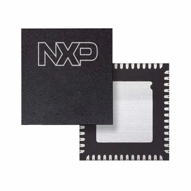
The NXP TJA1102AHN/0Z is a full-duplex Ethernet transceiver supporting 100 Mbps data rate over standard twisted-pair cabling. It integrates two independent transmit and receive channels (2/2 driver/receiver count) in a single 56-HVQFN (8x8 mm) package, making it a dense solution for multi-port automotive or industrial Ethernet nodes. The part operates from a dual supply rail of 1.8V and 3.3V, and its -40°C to 125°C temperature range qualifies it for under-hood and other high-temperature environments where consumer-grade transceivers would not survive.
Temperature range and what it means for deployment
That 125°C upper limit is the junction temperature typical of automotive-grade Ethernet PHYs used in engine-adjacent ECUs, ADAS camera modules, or industrial motor drives that see sustained heat soak. A part rated only to 85°C or 105°C would risk link drops or permanent failure in those bays.
For procurement, this removes the single-source risk of chasing a discontinued part through the spot market.
Package and supply rail considerations for layout
The 56-VFQFN exposed-pad package (supplier device package 56-HVQFN, 8x8 mm) requires a thermal pad land pattern and via stitching to the ground plane for heat dissipation, especially when both channels are active at 125°C ambient. The dual supply rails (1.8V for the digital core, 3.3V for the analog PHY) need separate decoupling and a clean power-up sequence; the datasheet's recommended supply ramp order should be followed to avoid latch-up or undefined state on the MII/RMII interface.