What the 400kHz data rate means for your I²C bus
The NXP PCA9517DP,118 is a single-channel I²C buffer and reDriver that operates at a maximum data rate of 400kHz, covering standard-mode (100kHz) and fast-mode (400kHz) I²C buses. The 400kHz ceiling is the bus speed limit after the reDriver's propagation delay and rise-time acceleration are factored in — if your downstream devices are rated for 1MHz fast-mode plus, this buffer becomes the bottleneck, not the bus. Two channels are available, but the part is a single-channel buffer meaning it buffers one bidirectional I²C line (SDA or SCL) per channel. For a full I²C bus you need two channels — one for SDA, one for SCL — which this device provides in one package.
Supply range and voltage-level translation
The input capacitance is 6 pF, which is low enough to stay within the I²C bus capacitive load limit of 400 pF for fast-mode even when multiple devices are on the segment. Supply current draw is 5mA — this is the quiescent current into the VCC pin when the bus is idle. During active data transfer the current spikes higher as the reDriver's rise-time accelerator engages, but the 5mA figure is what you budget for the static power rail.
Temperature grade and deployment context
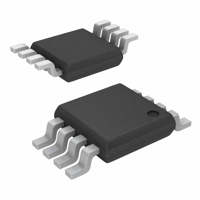
The 8-TSSOP package is a 3.00 mm × 4.40 mm body with 0.65 mm pitch, which routes comfortably on a two-layer PCB without micro-vias. The Tape & Reel packaging is the standard 2,500-piece reel for the 8-TSSOP footprint.