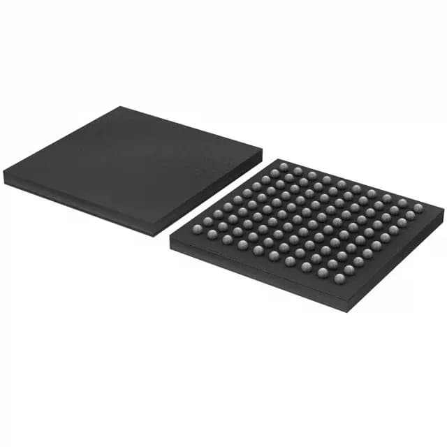
NXP LPC18S10FET100E — ROMless ARM Cortex-M3 MCU, 180MHz, 100-TFBGA
NXP LPC18S10FET100E, ROMless 32-bit ARM Cortex-M3 MCU, 180MHz, 136K RAM, 49 I/O, CAN, EBI, SPI, MMC/SD, 4×10-bit ADC / 1×10-bit DAC, 2.2–3.6V supply, -40 to 85°C, 100-TFBGA (9×9 mm) in tray.
- 100% new & originalTraceable channels only — no refurbs, no pulls, no remarked parts.
- Date & lot codes on quoteStated per line before you commit; label photos on request.
- MSL-compliant ESD packingMoisture-sealed bags with indicator cards; reels photo-verified.
- PayPal buyer protectionPay by T/T, PayPal or Payoneer — card payments covered end to end.
Specifications
| Parameter | Value |
|---|---|
| Series | LPC18xx |
| Mounting type | Surface Mount |
| Oscillator type | Internal |
| Program memory type | ROMless |
| Voltage - supply (Vcc (Vdd)) | 2.2V ~ 3.6V |
| Operating temperature | -40°C~85°C(TA) |
| Speed | 180MHz |
| Package | Tray |
| RAM size | 136K x 8 |
| Core size | 32-Bit Single-Core |
| Peripherals | Brown-out Detect/Reset, DMA, I²S, POR, WDT |
| Connectivity | CANbus, EBI/EMI, I²C, IrDA, Microwire, MMC/SD, SPI, SSI, SSP, UART/USART |
| Number of i (O) | 49 |
| Core processor | ARM® Cortex®-M3 |
| Case | 100-TFBGA |
| Data converters | A/D 4x10b; D/A 1x10b |
Frequently asked questions
What external flash does the LPC18S10FET100E require, and is there a validated companion part?
The part is ROMless and requires an external flash device on the EBI (parallel NOR) or SSI/SPI bus to host boot code and application firmware. The EBI supports zero-wait-state execution at 180MHz; SPI flash on the SSI is lower pin-count but reduces headroom at full clock speed. NXP's LPC18xx bootloader supports a specific list of validated flash IDs — consult the LPC18xx Flash Algorithm documentation to confirm your chosen flash part is on the supported list before finalising the BOM line.
Does the -40 to 85 °C rating hold in a sealed IP67 enclosure running at 180MHz with no forced-air cooling?
The -40 to 85 °C rating is the ambient temperature boundary, not the silicon junction limit. At 180MHz full-load in a sealed enclosure, the actual PCB and junction temperature depend on thermal resistance from the TFBGA package to ambient, which the 100-TFBGA's compact 9×9 mm footprint does not favour. If your enclosure runs above 60 °C ambient, derating the core speed or adding a thermal management strategy is the safe call — the datasheet thermal resistance data governs the exact derating curve.