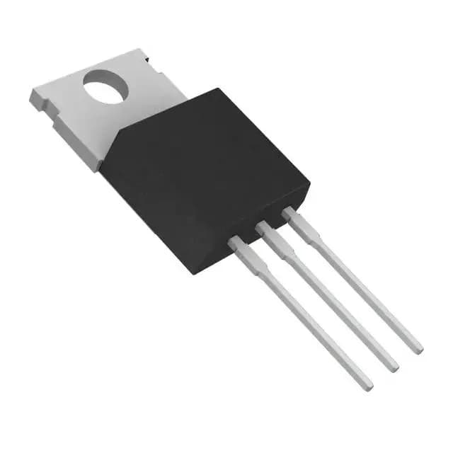
8 mOhm Rds(on) — conduction loss and heatsink sizing
At 75 A continuous current, the conduction loss alone reaches 45 W, which the 254 W package dissipation ceiling can handle only with aggressive heatsinking and forced airflow. In practice, most designs will run this part at 30–50 A continuous and rely on the low Rds(on) to keep junction rise under 40 °C above ambient. The 4 V threshold voltage at 1 mA means the device turns on fully with a standard 10 V gate drive; at 5 V gate drive the Rds(on) roughly doubles, so a logic-level driver is not recommended.
175 °C junction — under-hood margin and derating
The -55 °C to 175 °C operating junction temperature range is the reason this part works in engine-bay and transmission environments. The 175 °C max allows a 40 °C safety margin above a typical 125 °C ambient under the hood, but every degree above 25 °C derates the continuous current and the safe operating area. The 4352 pF input capacitance at 25 V Vds and 76 nC gate charge at 0 V Vgs are moderate — a standard automotive gate driver with 2 A peak current can switch the gate in about 100 ns, but the buyer should verify the driver's sink/source capability against the gate charge curve at the target switching frequency.
For a production program that needs a 55 V, 75 A automotive FET in a TO-220AB footprint, this part is available through franchised distribution and independent channels without the allocation risk that sometimes hits high-volume automotive MOSFETs. The AEC-Q101 qualification means the part has passed the full automotive stress test suite (H3TRB, HTRB, TC, etc.), so no separate qualification run is needed for Tier-1 programs.