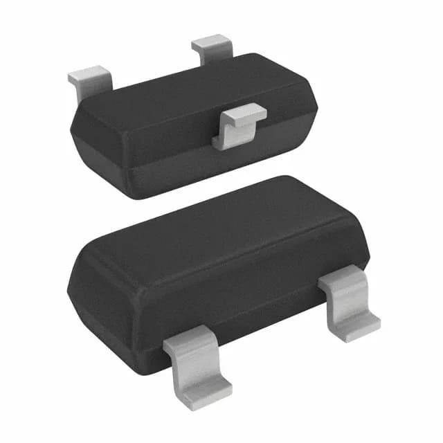
NXP Semiconductors BAP64-05W,115

NXP BAP64-05W,115 PIN Diode, 100V, 0.35pF, SC-70

MPNBAP64-05W,115
End of Life

NXP BAP64-05W,115, RF PIN diode, 1 pair common cathode, 100 V peak reverse, 100 mA max, 0.35 pF @ 20 V, 1.35 Ω @ 100 mA, SC-70 (SOT-323) package, -65 to 150 °C junction, 240 mW, ROHS3, Active.

$0.39Ref. price · indicative, final on quote
PackagingSC-70, SOT-323
StockContact for availability
MOQ1 pcs
  • 100% new & originalTraceable channels only — no refurbs, no pulls, no remarked parts.
  • Date & lot codes on quoteStated per line before you commit; label photos on request.
  • MSL-compliant ESD packingMoisture-sealed bags with indicator cards; reels photo-verified.
  • PayPal buyer protectionPay by T/T, PayPal or Payoneer — card payments covered end to end.

Specifications

BAP64-05W,115 Technical Specifications
ParameterValue
Diode typePIN - 1 Pair Common Cathode
Voltage - peak reverse100V
Current - max100 mA
Power dissipation240 mW
Operating temperature-65°C ~ 150°C (TJ)
PackageTape & Reel (TR); Cut Tape (CT)
CaseSC-70, SOT-323
Resistance @ if, f1.35Ohm @ 100mA, 100MHz
Capacitance @ vr, f0.35pF @ 20V, 1MHz

Product details

RF switch and attenuator workhorse in a common-cathode pair

The NXP BAP64-05W,115 is a silicon PIN diode configured as a common-cathode pair in a single SC-70 (SOT-323) package. It is specified for RF switching, attenuator, and limiter circuits from HF through low-GHz bands, where its 0.35 pF capacitance at 20 V and 1.35 Ω series resistance at 100 mA define the off-state isolation and on-state insertion loss, respectively.

Parametric anchor — capacitance and resistance at the bias point

The off-state capacitance is 0.35 pF measured at 20 V reverse bias and 1 MHz. That figure sets the isolation floor in a shunt-switch or series-shunt topology: at 1 GHz, 0.35 pF yields roughly 25 dB isolation per diode in a 50 Ω system, enough for most T/R-switch and antenna-diversity applications. Forward resistance drops to 1.35 Ω at 100 mA forward current, measured at 100 MHz. At that bias the diode is fully forward-biased and the insertion loss through a series-connected pair is under 0.3 dB in a 50 Ω path. Maximum continuous forward current is 100 mA, and total power dissipation is limited to 240 mW. The SC-70 package has a modest thermal footprint — derate the forward current if the ambient exceeds 85°C or if both diodes are biased simultaneously.

Package and mounting — SC-70 (SOT-323) footprint

The supplier device package is SC-70.

Frequently asked questions

What is the capacitance of BAP64-05W,115 at 20V?

This is the value that determines isolation in RF switch and attenuator circuits.

Is BAP64-05W,115 RoHS compliant?

Yes, it is ROHS3 compliant.

What is the resistance of BAP64-05W,115 at 100mA?

The forward series resistance is 1.35 Ω at 100 mA forward current, measured at 100 MHz. This is the on-state resistance that determines insertion loss in the forward-biased path.

Can BAP64-05W,115 replace BAP64-02W?

The BAP64-02W is a single PIN diode in a SOD-323 package, while the BAP64-05W,115 is a common-cathode pair in SC-70. They are not pin-compatible — the 05W replaces two single diodes in a series-shunt or π-configuration where a shared cathode node is acceptable, saving board area.