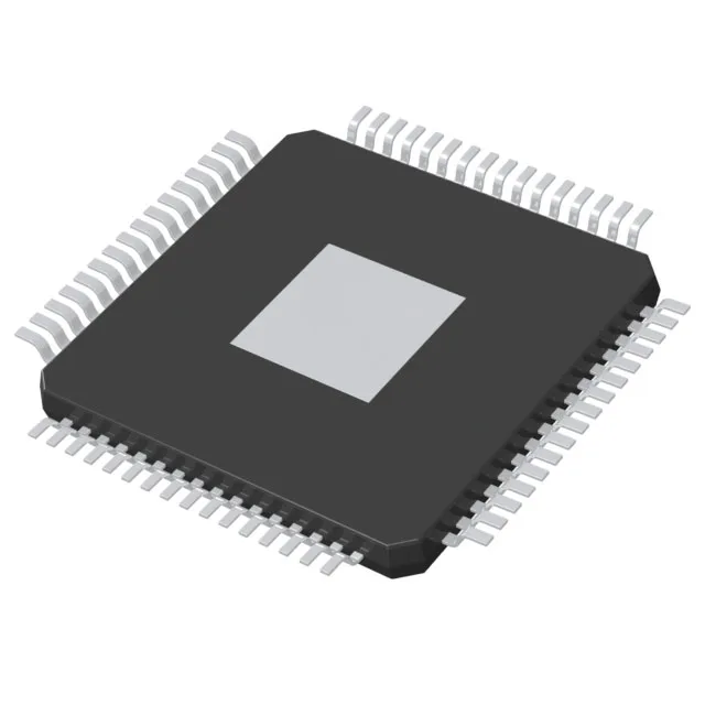
NXP LPC55S14JBD64E — ARM Cortex-M33 MCU, 150MHz, 128KB Flash, 64-HTQFP
NXP LPC55S14JBD64E, ARM Cortex-M33 150MHz, 128KB Flash / 80KB RAM, 36 I/O, CANbus / USB / SPI / UART, 10-channel 16-bit SAR ADC, 1.8–3.6V supply, -40 to 105°C, 64-HTQFP exposed pad tray.
- 100% new & originalTraceable channels only — no refurbs, no pulls, no remarked parts.
- Date & lot codes on quoteStated per line before you commit; label photos on request.
- MSL-compliant ESD packingMoisture-sealed bags with indicator cards; reels photo-verified.
- PayPal buyer protectionPay by T/T, PayPal or Payoneer — card payments covered end to end.
Specifications
| Parameter | Value |
|---|---|
| Series | LPC55S1x |
| Mounting type | Surface Mount |
| Oscillator type | Internal |
| Program memory type | FLASH |
| Voltage - supply (Vcc (Vdd)) | 1.8V ~ 3.6V |
| Operating temperature | -40°C ~ 105°C (TA) |
| Speed | 150MHz |
| Package | Tray |
| RAM size | 80K x 8 |
| Core size | 32-Bit Single-Core |
| Peripherals | Brown-out Detect/Reset, DMA, I²S, POR, PWM, RNG, WDT |
| Connectivity | CANbus, Flexcomm, I²C, SPI, UART/USART, USB |
| Number of i (O) | 36 |
| Core processor | ARM® Cortex®-M33 |
| Case | 64-TQFP Exposed Pad |
| Data converters | A/D 10x16b SAR |
| Program memory size | 128KB (128K x 8) |
Frequently asked questions
Can I source this part today, and what should I watch before committing a BOM line?
Sourcing is quoted-to-order through authorized channels. The 36 I/O count is the most common BOM trap on this part — designers expecting 48+ I/O from an STM32-class part should verify the pin-count budget before freeze. The 1.8–3.6 V supply rules out direct 5 V rail hookup. For enclosed-panel or cabinet deployments above 85 °C ambient, the 105 °C upper limit provides headroom, but NXP's thermal resistance and derating curves for the 64-HTQFP exposed pad are datasheet territory — confirm with your NXP FAE or through the RFQ channel.
What is the package and does the exposed thermal pad create rework risk?
The LPC55S14JBD64E comes in a 64-HTQFP (10×10 mm) with an exposed thermal pad, supplied on tray. The exposed pad must be soldered during assembly and rework — it is not a socketed part. Boards using the LPC55S16JBD64 footprint may share the same pad geometry, but pin compatibility between the two variants is datasheet-verified territory; confirm the pinout match before dropping in as a replacement. For rework on existing joints, the thermal pad creates flux-wicking risk — a hot-air station with proper temperature profiling is required.