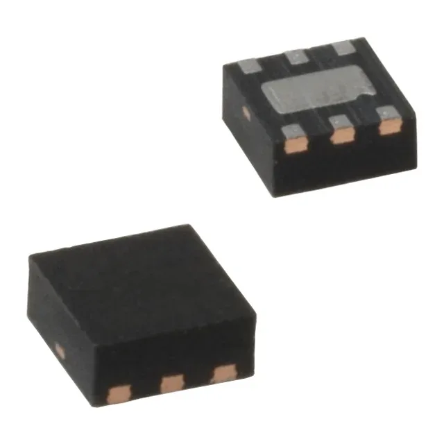
Dual 300 mA rails in a 1.6x1.6 mm TMLF
The MIC5335-SMYMT-TR packs two independent 300 mA LDOs in a 6-TMLF package measuring 1.6x1.6 mm with an exposed thermal pad. Outputs are fixed at 2.8 V and 3.3 V — a common pairing for powering a 3.3 V digital core and a 2.8 V analog or memory rail from a single 5.5 V max input. Each regulator drops only 200 mV at full load, so a 3.3 V rail needs at least 3.5 V input to stay in regulation. The 125 µA quiescent current per channel (220 µA max total) keeps the self-consumption low for battery-powered gear that spends most of its time in a light-load state.
PSRR across the audio band — what 65 dB to 45 dB means
Power-supply rejection ratio is specified at 65 dB at 1 kHz, rolling to 45 dB at 20 kHz. That 20 dB drop across the audio band means the regulator attenuates 1 kHz ripple by a factor of ~1800 but only ~180 at 20 kHz. For a sensitive audio-codec or ADC supply, the upstream switching converter's ripple at 2-3 MHz is already well above the PSRR roll-off — a post-filter LC stage ahead of the LDO is still advisable if the noise floor matters below -80 dBV.
Protection features and board-fit checklist
Over-current and over-temperature protection are built in — the LDO folds back current on a short and shuts down if the die exceeds the thermal limit. The Enable pin lets a system sequencer turn each rail on independently, avoiding inrush collisions on a shared input capacitor. The 6-TMLF package (1.6x1.6 mm, 0.5 mm pitch) demands a solder-paste stencil aperture that matches the exposed pad for void-free reflow. The supplier device package is designated 6-TMLF (1.6x1.6) — the PCB land pattern should follow Microchip's recommended footprint to keep the thermal resistance below 60°C/W.
No pin-compatible second source is listed on the record — the dual-fixed-output 2.8V/3.3V combination is specific to this Microchip order code.