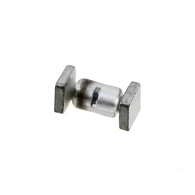
27 V breakdown, 500 W peak pulse — Zener TVS in SQ-MELF
Its minimum breakdown voltage is 27 V, clamping at 41.4 V max with a peak pulse current of 69 A under the 8/20 µs waveform. The single-channel design protects one rail against positive-going transients. The SQ-MELF B package is a leadless cylindrical ceramic body — no solder tails, so the pad footprint is compact and the thermal path is through the end caps.
With a clamping voltage of 41.4 V at 69 A (8/20 µs), the 1N6465US leaves a margin above the 27 V breakdown threshold. That margin is typical for a Zener TVS — the downstream circuit must tolerate the clamp voltage without latch-up or damage. The 500 W peak pulse power rating is the energy-handling ceiling; for shorter pulses the device absorbs more current before failing. Because the part is unidirectional, it only clamps one polarity. If the protected line carries a negative swing relative to ground, a bidirectional TVS or back-to-back series pair is required. No power line protection is built in — this is a signal-rail suppressor, not a mains-grade MOV replacement.
The package is format — not tape-and-reel. For automated pick-and-place, a reel or tray variant may need to be sourced separately if the BOM calls for machine placement. Confirm the packaging code with your distributor before committing the line.
SQ-MELF rework — what to expect at the bench
The SQ-MELF B package is a surface-mount ceramic cylinder with metallised end caps — no gull-wing leads, no J-bends. Rework requires hot air; the part lifts cleanly when both end-cap solder joints are molten simultaneously. The small thermal mass means it heats quickly, but the ceramic body can crack if the temperature ramp is too aggressive. Use a preheat plate and a hot-air nozzle to avoid thermal shock. Pad layout is a simple two-terminal footprint with no centre tab. Polarity is marked by a band on the cathode end — confirm orientation before placement. The MELF body rolls during reflow if the solder paste deposit is uneven; stencil aperture design should centre the paste under each end cap.