What the standoff and clamping ratings mean for your line
The 5.0SMDJ45A-T7: The 45V reverse standoff (typ) is the working voltage the protected telecom rail sits below without the TVS conducting — the line runs at a nominal voltage safely below this so the device stays off during normal operation. When a surge exceeds 50V breakdown minimum, the device clamps at 72.7V maximum, limiting what the downstream IC sees to that ceiling regardless of how hard the transient pushes — that 72.7V is the protection budget the load must survive. 68.8A peak pulse at the 10/1000µs wave shape is the current the diode handles during the clamping event; the 5000W rating is the peak pulse power envelope the package dissipates during that same transient — both specs must clear the surge profile of the target telecom equipment.
DO-214AB package and rework checklist
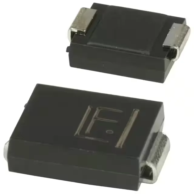
The DO-214AB (SMC) supplier package is a standard SMC footprint — the cathode band marks polarity on the sleeve, so orientation is unambiguous under magnification before reflow. Surface-mount termination on a copper pad with standard SAC or Sn leadfree solder profile — the die is mounted to the die-attach flag inside the mold compound, so the thermal path from junction to pad is direct; a hot-air nozzle at 260 °C with preheat to 150 °C on the board lifts the part without cooking the surrounding traces. Operating junction temperature runs to 150 °C — the board-level rework temperature ceiling is set by the adjacent components, not the TVS itself; stay below 235 °C peak reflow on the pad and the die attach holds.
Telecom deployment context and sourcing posture
Listed under Telecom as the primary application — the standoff and clamping ratings target telecom infrastructure rails where lightning-surge ingress and transient spike clamping are the design constraint.