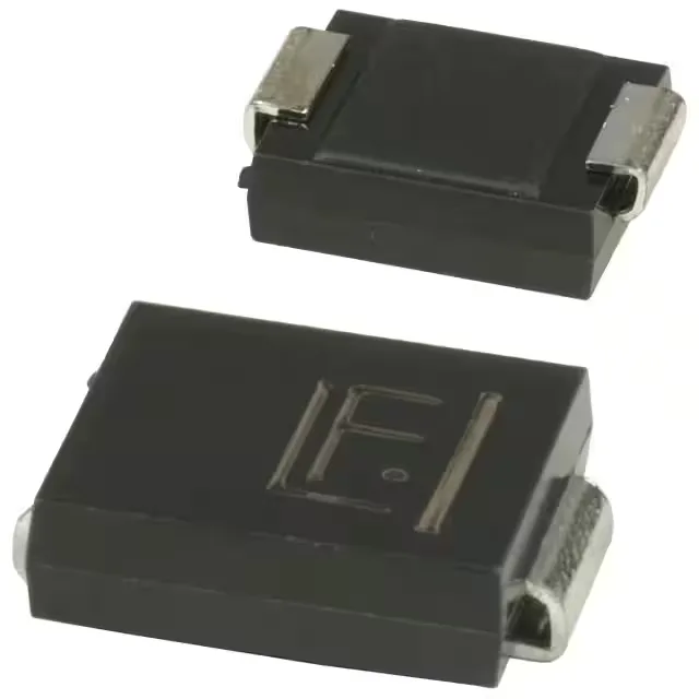
What 12.1V clamping means for the protected rail
The 1.5SMC8.2A: With 125.6 A peak pulse current and a typ 7.02 V standoff, the clamping ceiling of 12.1 V is what the downstream circuit sees during a surge event — so a 5 V rail stays below its absolute-maximum during the clamping window. The minimum breakdown of 7.79 V sits above the 7.02 V standoff, giving the circuit normal operating headroom — the device stays off and leakage is negligible until the transient pushes the rail past breakdown. Operating junction temperature runs to 150 °C, which handles the self-heating spike during a clamping event without derating for most panel-level deployments.
SMC package and board-level fit
The DO-214AB SMC is a standard surface-mount package with a wide copper pad under the cathode tab — thermal resistance from junction to ambient is set by the pad solder joint and board copper area, not the housing. The supplier device package is listed as SMCJ, which is the common industry designation for this footprint; confirm the landing pattern matches the datasheet land pattern for the cathode-anode spacing before committing a new layout. Tape-and-reel and cut-tape packaging suit both high-volume placement and small-batch rework — the DO-214AB is reball-ready for BGA-adjacent replacement scenarios, and the surface-mount form factor accepts standard hot-air or IR rework profiles.
Active sourcing posture
The 1.5SMC series is a long-running Littelfuse family, so second-source alternatives in the same SMCJ footprint are typically available from competing TVS suppliers if BOM hedge is a concern. Confirm the standoff and clamping specs match the legacy Littelfuse values before swapping, since TVS breakdown grading can vary between manufacturers.